Energy of Electrons and Photons (ECAL)
Energy of Electrons and Photons (ECAL) lucas
In order to build up a picture of events occurring in the LHC, CMS must measure the energies of emerging particles. Of particular interest are electrons and photons, because of their use in discovering the Higgs boson and other new physics.
The energies of electrons and photons are measured using the CMS electromagnetic calorimeter (ECAL). Measuring their energies with the necessary precision in the very strict conditions of the LHC - a high magnetic field, high levels of radiation, and only 25 nanoseconds between collisions - requires dedicated detector materials.
Lead tungstate crystal is made primarily of metal and is heavier than stainless steel, but with a touch of oxygen in this crystalline form, it is highly transparent and “scintillates” when electrons and photons pass through it. This means it produces light in proportion to the impinging particle’s energy. These high-density crystals produce light in fast, short, well-defined photon bursts that allow for a precise, fast, and fairly compact detector.
Photodetectors, which have been especially designed to work within the high magnetic field, are glued onto the back of each of the crystals to detect the scintillation light and convert it to an electrical signal that is amplified and sent for analysis.
The ECAL, made up of a “barrel” section and two “endcaps”, forms a layer between the tracker and the HCAL. The cylindrical barrel consists of 61,200 crystals formed into 36 “supermodules”, each weighing around three tonnes and containing 1700 crystals. The flat endcaps seal off the barrel at each end and are made up of almost 15,000 more crystals.
For extra spatial precision, the ECAL also contains a preshower detector that sits in front of the endcaps. These allow CMS to distinguish between single high-energy photons (often signs of exciting physics) and the less interesting close pairs of low-energy photons.
The CMS ECAL…
- crystals each weigh 1.5kg but with a volume roughly equal to that of a small coffee cup,
- contains nearly 80,000 such crystals, each of which took two days to grow.
CMS ECAL Technical Design Report
Production Story ....
A Russian factory in a former military complex took on the job of producing most of the crystals, while the remainder were produced in China. It took about ten years to grow all 78,000 crystals to stringent specifications, taking around two days to grow each one. Inside the detector, the crystals face high radiation, so the lead tungstate material had to be carefully chosen and developed.
Crystal Calorimeter
Crystal Calorimeter lucas
CMS uses lead tungstate (PbWO4) for the almost 80,000 crystals: a material with high density that produces scintillation light in fast, small, well-defined photon showers. This means the calorimeter system can be very precise and very compact, fitting within the CMS superconducting magnet. Lead tungstate is also relatively easy to produce from readily available raw materials, and the experience and capability to manufacture them already existed in China and Russia.
Of course, the material also has drawbacks: firstly that the yield of light depends strongly on temperature, a problem given how much heat is released by the readout electronics. To solve the cooling problem a custom-built system maintains the temperature of the 100 tonnes of crystal to within 0.1oC.
Additionally, because the yield of light output is low,the scintillation light [see explanation below] must be captured by photodetectors, converted to an electrical signal, and then amplified. The stronger and now digitised electrical signals are then transmitted through optic fibres. Because the photodetectors also need to be radiation hard and operate within a strong magnetic field, avalanche photodiodes or APDs [see explanation below] were selected for the crystal barrel, and vacuum phototriodes (VPTs) for the endcaps.
Finally, though already fairly radiation resistant after intense research to purify the material, researchers found that lead tungstate would still suffer limited radiation damage inside CMS. However the R&D programme led to a much better understanding of how this damage occurs and found that its main effect is to colour the crystal, affecting how light travels through it.
Knowing this, physicists can ensure that they allow for it in their analysis using a “light monitoring system” during operation that sends pulses of light through each crystal to measure its “optical transmission”. The crystals can reverse radiation damage, or “anneal”, when the accelerator stops (when they are at room temperature) as the warmer temperature naturally shakes atoms back into their ordered structure.
Getting the material right was only one of the challenges for the ECAL team; each crystal had to be cut, machined, polished, tested,and attached to a photodetector. Groups of crystals were then assembled side-by-side in glass-fibre or carbon-fibre “pockets” to form larger structures known as “supercrystals”, “modules”, and “supermodules”.
Crystal Facts
- Crystals measure 2.2 x 2.2 x 23 cm in the barrel and 3 x 3 x 22 cm in the endcaps
- There are exactly 75,848 crystals in the ECAL
- The density of lead tungstate is 8.3 g/cm3
What is scintillation?
When an atom is excited, that is, given energy, an electron goes into a higher orbit and then when it falls back, it releases this energy as a photon. In CMS, when a high-energy electron or photon collides with the heavy nuclei of the ECAL crystals, it generates a shower of electrons, positrons, and photons, and atoms in the material take energy from the passing particles to excite their electrons. The atoms quickly ‘relax’ and the electrons each emit the extra energy as a photon of blue light. A photo device [see below] then picks up these ‘scintillation’ photons and the amount of light generated is proportional to the energy that was deposited in this crystal. This tells us the energy of the incoming electron or photon.
What are photodetectors?
Avalanche photodiodes (APDs) are photodetectors made of semiconducting silicon with a strong electric field applied to them. When a scintillation photon strikes the silicon and knocks an electron out of an atom, the electron is accelerated in the electric field, quickly striking other atoms and knocking electrons off those too. As these are also accelerated, this method will produce an avalanche of electrons with their numbers increasing exponentially. Through this method, APDs are able to produce a very high current in a short time, which is necessary as the lead tungstate crystals give a relatively low light yield for each incident particle. The signal is then amplified, digitised and immediately transported away by fibre optic cables, so that the analysis can be done away from the radiation area.
Crystals in the endcaps use vacuum phototriodes (VPTs) because here the radiation is too high to use silicon photodiodes. As opposed to an APD, a VPT contains three electrodes within a vacuum. Initially, electrons are released when the light strikes atoms in the first electrode in the normal way. Then the voltage difference between electrodes accelerates the electrons into the second electrode (the anode), producing several more electrons, that are all then accelerated to the third (the dynode), releasing a second batch of electrons. Thus this also creates a large current from the initial tiny amount of scintillation light, which is turned into a digital signal and sent along the optic fibres to the upper level readout.
All the photodetectors were glued to the crystals here at CERN, but the finished products are the sum of contributions made by several hundred people and many institutes.
ECAL Preshower
ECAL Preshower lucas
One way the Higgs boson might decay is into high-energy photons and detecting them is one of the ECAL’s primary functions. However, short-lived particles called neutral pions, also produced in collisions, can inadvertently mimic high-energy photons when they decay into two closely-spaced lower energy photons that the ECAL picks up together.
In the endcap regions, where the angle between the two emerging photons from the decay of a neutral pion is likely to be small enough to cause this problem, a preshower detector sits in front of the ECAL to prevent such false signals. The preshower has a much finer granularity than the ECAL with detector strips 2 mm wide, compared to the 3 cm-wide ECAL crystals, and can measure each of the pion-produced particles as a separate photon.
The preshower is made of two planes of lead followed by silicon sensors, similar to those used in the CMS tracker. When a photon passes through the lead layer it causes an electromagnetic shower, containing electron-positron pairs, which the silicon sensors then detect and measure. From this we get a measure of the photon’s energy, while having two detector layers gives us two measurements, allowing us to pinpoint the particle’s position.
When seemingly high-energy photons are then found in the ECAL, we can extrapolate their paths back to the centre of the collision and look for their “hits” in the preshower along the way, adding the energy deposited there to the total energy from the ECAL, and deducing if they really were individual high-energy photons or photon pairs.
Each endcap preshower uses 8 square metres of silicon (a material especially chosen for its accuracy, compactness, ability to deal with radiation, and easiness to handle). The silicon sensors, each measuring about 6.3cm x 6.3cm x 0.3mm and divided into 32 strips, are arranged in a grid in the endcaps to form an approximately circular shape covering most of the area of the crystal endcap. For optimal performance during the lifetime of the experiment, as in the tracker, the silicon detectors must be kept at a temperature of between -10oC and -15oC. However, the nearby ECAL is very sensitive and must be kept within precisely 0.1oC of its (higher) optimal temperature. The preshower must therefore be cold on the inside but warm on the outside, achieved using both heating and cooling systems.
The complete preshower system forms a disc, about 2.5m in circumference with a 50cm diameter hole in the middle (through which the beam pipe passes). This disc is only 20cm thick but manages to squeeze inside two layers of lead, two layers of sensors (and their electronics) as well as the cooling and heating systems – another example of the “compact” nature of CMS.
Energy of Hadrons (HCAL)
Energy of Hadrons (HCAL) lucas
The Hadron Calorimeter (HCAL) measures the energy of “hadrons”, particles made of quarks and gluons (for example protons, neutrons, pions and kaons). Additionally it provides indirect measurement of the presence of non-interacting, uncharged particles such as neutrinos.
Measuring these particles is important as they can tell us if new particles such as the Higgs boson or supersymmetric particles (much heavier versions of the standard particles we know) have been formed.
As these particles decay they may produce new particles that do not leave records of their presence in any part of the CMS detector. To spot these the HCAL must be “hermetic”, that is make sure it captures, to the extent possible, every particle emerging from the collisions. This way if we see particles shoot out one side of the detector, but not the other, with an imbalance in the momentum and energy (measured in the sideways “transverse” direction relative to the beam line), we can deduce that we’re producing “invisible” particles.
To ensure that we’re seeing something new, rather than just letting familiar particles escape undetected, layers of the HCAL were built in a staggered fashion so that there are no gaps in direct lines that a familiar particle might escape through.
The HCAL is a sampling calorimeter [see explanation below] meaning it finds a particle’s position, energy and arrival time using alternating layers of “absorber” and fluorescent “scintillator” materials that produce a rapid light pulse when the particle passes through. Special optic fibres collect up this light and feed it into readout boxes where photodetectors amplify the signal. When the amount of light in a given region is summed up over many layers of tiles in depth, called a “tower”, this total amount of light is a measure of a particle’s energy.
As the HCAL is massive and thick, fitting it into “compact” CMS was a challenge, as the cascades of particles produced when a hadron hits the dense absorber material (known as showers) are large, and the minimum amount of material needed to contain and measure them is about one metre.
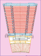
To accomplish this feat, the HCAL is organised into barrel (HB and HO), endcap (HE) and forward (HF) sections. There are 36 barrel “wedges”, each weighing 26 tonnes. These form the last layer of detector inside the magnet coil whilst a few additional layers, the outer barrel (HO), sit outside the coil, ensuring no energy leaks out the back of the HB undetected. Similarly, 36 endcap wedges measure particle energies as they emerge through the ends of the solenoid magnet.
Lastly, the two hadronic forward calorimeters (HF) are positioned at either end of CMS, to pick up the myriad particles coming out of the collision region at shallow angles relative to the beam line. These receive the bulk of the particle energy contained in the collision so must be very resistant to radiation and use different materials to the other parts of the HCAL.
The CMS HCAL…
- used over a million World War II brass shell casings from the Russian Navy in making some of its detector components;
- is made up of 36 wedges, each of which weighs as much as 6 African elephants;
- contains over 400 “optical decoder” units, all of which were made by American high school students through the QuarkNet programme.
For a detailed account of the HCAL detector see:
CMS Technical Design Report for the Phase 1 Upgrade of the Hadron Calorimeter https://cds.cern.ch/record/1481837/files/CMS-TDR-010.pdf
CMS HCAL Technical Design Report (1997)
HCAL Sampling Calorimeter
The CMS barrel and endcap sampling calorimeters are made of repeating layers of dense absorber and tiles of plastic scintillator. When a hadronic particle hits a plate of absorber, in this case brass or steel, an interaction can occur producing numerous secondary particles. As these secondary particles flow through successive layers of absorber they too can interact and a cascade or “shower” of particles results. As this shower develops, the particles pass through the alternating layers of active scintillation material causing them to emit blue-violet light. Within each tile tiny optical “wavelength-shifting fibres”, with a diameter of less than 1mm, absorb this light. These shift the blue-violet light into the green region of the spectrum, and clear optic cables then carry the green light away to readout boxes located at strategic locations within the HCAL volume.
A megatile is a layer of tiles whose sizes depend on their spatial location and orientation relative to the collision, chosen so that each receives roughly the same number of particles. Optic fibres fit into grooves cut into the individual tiles. Because the light picked up gives a measure of energy, the gaps between tiles must be filled with a reflective paint to ensure that light produced in each tile cannot escape into others and vice versa.
HCAL module showing sampling layers
The optical signals arrive at the readout boxes from megatile layers. There, signals from successive tiles, one behind the other, are then added optically to form “towers”. This optical summation covers the path of the particle through the HCAL and is a measure of its energy and/or can be an indicator of particle type.
These summed optical signals are converted into fast electronic signals by photosensors called Silicon Photomultipliers (SiPMs) . Special electronics then integrates and encodes these signals and sends them to the data acquisition system for purposes of event triggering and event reconstruction.
SiPMs are photodetectors configured especially for CMS that can operate in any magnetic field and give an amplified response, in proportion to the original signal, for a large range of particle energies. The SiPMs are housed in special readout boxes within the calorimeter volume. Light signals from the calorimeter megatiles are delivered to the SiPMs by special fibre-optic waveguides.
Using Russian navy shells
Using Russian navy shells Anonymous (not verified)
Constructing the endcap HCAL (HE) was the responsibility of the Russian and Dubna (RDMS) groups. The endcaps consist of 17 layers of dense absorber plates that take energy from hadrons and muons emerging from collisions and, together with plastic scintillator plates, give a measure of the particles’ energies.
Because the plates are so large and heavy the teams knew that within the experiment they would be under high levels of stress; yet, to maintain their position relative to the beam pipe for as long as 15 years, they couldn’t bend. The material eventually chosen for the plates was brass, in layers 50 mm thick.
But they needed brass of such high quality that it was practically impossible to find and was an expensive material. When Russian engineers discussed the question, one remembered a study carried out on the properties of brass made for military artillery use that sounded promising.
In Russian military storage there were thousands of shells made of brass that would fit such stringent requirements – all 50 years old, made by the Navy and designed to stand internal high stress and sea storage aboard a 1940s Navy Vessel. The shells could be melted for use in the HCAL.
The first hurdle involved obtaining permission of the Commander of the Navy, never easy, but who in fact agreed fairly quickly. Fifteen navy arsenals began recycling their shells, many being off-loaded from battleships in Murmansk to begin their new scientific life as absorber plates within CMS.
First the shells were sent to a plant in the North of Russia to be disarmed of their explosive contents. The shell casings were then stored at JSC Krasnyj Vyborzhets in St. Petersburg before being melted down and rolled into plates, a difficult process given that the brass was already semi-processed.
Over a million World War II brass shell casings were melted down to make the detector components. But when even this fell short of the massive 600 tonnes of brass needed to make the endcaps, the US agreed to provide a further $1 million in copper (brass being an alloy of copper and zinc) to complete the endcaps. As an example of the international cooperation and mutual trust fostered through this work, even this deal was agreed to on an amicable "handshake" basis.
In Minsk, Belarus, the brass was machined into absorber plates and finally pre assembled into parts of the endcaps, weighing 300 tonnes each, before being sent to CERN. Dollezhal Research and Development Institute of Power Engineering (NIKIET) coordinated the efforts of the Northern Navy and the companies involved, and ran 1400 tests to ensure the material was of high quality and suitable for constructing the endcap HCALs.
The shells and additional copper became a total of 1296 brass pieces, which were delivered to CERN in 2002 and 2003 and have since been installed and tested within CMS.
This project was part of an international agreement to convert Russian military industry into peaceful technology. The recycling of stocks of ship artillery into materials for fundamental research was also symbolic; instead of being used to destroy, the weapons could actively benefit humankind through their contribution to enhanced knowledge and technology.
The crystal story
The crystal story lucas")
A crystal’s journey from creation to its place within the CMS electromagnetic calorimeter is an arduous one: its trials include travelling thousands of miles, being sawed and polished, as well as being heated to 1,165oC and cooled to 18oC.
The journey starts in either a disused military complex in Bogoroditsk, Russia, or the Shanghai Institute of Ceramics (SIC) in China. These two institutions together took on the job of producing the 78,000 crystals to stringent specifications. Crystals are grown around a tiny “seed” - an existing piece of the crystal with the required properties - from a 1,165oC melt of tungsten oxide, lead oxide and “doping” materials, small amounts of other materials that refine the crystals’ properties.
In the Russian method, the seed is pulled from the scalding mixture at a very slow, precise speed that allows the atoms of the melt to arrange into a crystal structure around it. “In 2 or 3 days you have your crystal, which may seem slow but it’s quick compared to geology,” explains Michel Lebeau, an engineer in the crystals team.
Dusting with diamond
But the raw form of the crystal still needs a makeover before it can become one of the sparkling gems we see in the experiment. First it must be cut, ground and polished with diamond. Diamond is the hardest naturally occurring material and can scratch or cut through other crystals, allowing them to be shaped.
A disc covered with fine diamond grains first cuts the crystals’ prismatic accurate shape from its original round form. The second stage, called lapping, involves grinding the rough sides of the crystal as if with diamond sandpaper - a sprayed diamond suspension coats a rotating table, similar to a potter’s wheel, and as the crystals pass over it their surfaces are sanded to a fine matte finish, the flatness of which is controlled to less than a fraction of the width of a human hair.
Finally, to replace the crystals’ cloudy surfaces with a transparent finish, they must now pass over an even finer suspension of diamond, as finer abrasive gives an even smoother surface. The grains used here are in fact so tiny that the polished surface pattern is smaller than the wavelength of light.
To ensure a perfect match with the neighbouring crystals, and to give accurate measures of particle energies, each crystal must comply with very accurate dimensions so that they react in exactly the same way to the light. To make sure of this, the machines that transform the crystals into their sleek final form must also be fine-tuned and precise. After extensive research and development, machines that could give these perfect finishes were designed, fabricated locally and finally shipped, installed and ran at production sites in Russia and China.
Into the detector
For the crystals arriving at the regional centres in CERN and Rome, the welcome was warm but testing was thorough, as each had to be vetted before becoming part of the detector.
The arriving crystals were first unpacked and identified with a barcode before a visual inspection checks for any visible defects. Finally they were registered into a database so they could be followed throughout production and their lifetime in CMS.
Then the dimensions, light transmission and scintillation properties of the crystals were measured, 30 at a time, in an automatic machine (ACCOS) developed in both regional centres. “Usually with a crystal, the beauty of it is that it is coloured. But in our case if crystals are coloured would mean defects and reduced performance,” explains Etiennette Auffray, leader of the crystal assembly at CERN. But in fact only a very small number (less than 1%) of the 1200 crystals processed every month proved unsuitable for use
The vast majority of crystals made it through and were then carefully glued with a photodetector, which will collect and amplify their scintillation light and convert the light into an electrical signal. Each photodetector was then housed in one of 22 slightly different varieties of capsules and glued to one of 34 categories of crystal, in total making 146 different possible combinations: “So there’s a lot of scope to go wrong! We have to check it very carefully after each stage,” explains Auffray.
Then, like building blocks, the crystals were grouped in increasing numbers – for the barrel section they are first packed into lightweight glass-fibre boxes in groups of ten, making a ‘sub-module’. A ‘module’ was then constructed out of 40 or 50 sub-modules.
These modules were then joined by those assembled at the INFN/ENEA Laboratory near Rome, which also carried out the crystal tests and the glueing of photodetectors, in tandem with CERN. These were packed in groups of four, making one of the 36 “supermodules”, each of which weighs 2.5 tonnes.
For the endcaps, 25 crystals are grouped in five-by-five blocks named “supercrystals” and inserted into one of four “Dees”, structures named for their resemblance to the letter D, that fit around the beam allowing easy installation.
Finally the monitoring, cooling system and final electronics were added to the supermodules before they entered the experiment cavern. The cooling system is a record-breaking achievement that keeps the 75,848 crystals within 0.1°C of their optimum temperature to ensure they give a stable and equal response. The flow of water needed to achieve this, recycled through the system, equals 1/10th of the output of Geneva’s Jet d’Eau (Geneva’s fountain).
Inside CMS the supermodules are supported on a strong but lightweight system, designed to add only a minimum amount of material in front of the detector. The structure and crystals are so densely and precisely packed that the remaining space is only 1% of the total. The 2.5-tonne weight of each supermodule is cantilevered from one end so that two-thirds of it is taken at the back and the remaining third on a slender arm of aluminium and glass fibre composite. The maximum expected sag, including in the event of (very improbable) earthquakes, is about half a millimetre. This structure accounts itself for just 10% of the total weight - like a car that carries four passengers weighing just 30kg!
The CRISTAL database
The CRISTAL database achintya
Each CMS crystal is unique even though they are all made from the same material. Its physical characteristics therefore needed to be measured and recorded, not only for the construction phase but also for data collecting itself. Every crystal was labelled with a barcode to identify it and track it through the production and operation stages.
The long time-frame of producing the crystals meant that the means of production as well as the associated electronics evolved over time as improvements were made. Themethods of characterising the crystals themselves and the data formats used for storage also evolved with time. The database into which the information was to be stored would itself need to adapt to these evolving workflows. At the same time, the database must be able to fetch all of the data ever recorded –– i.e. it must be capable of handling legacy datasets –– and must be in a situation to do so in the future when the implementation might potentially be very different. It would also have to handle frequent changes, and so be flexible in design.
No such system existed in the mid-'90s, and so a consortium of scientists from CERN, CNRS (the French National Centre for Scientific Research) and UWE (the University of the West of England) set about developing their own database, giving birth to CRISTAL.
CRISTAL stands for Cooperative Repositories and Information System for Tracking Assembly Lifecycles, and was developed at CERN to manage the data of all CMS ECAL components at each stage of construction.
The CRISTAL database and its underlying technology is extremely novel, and has applications far beyond the world of tracking detector components. CRISTAL is description-driven; that is, the database structures can be modified at any time without affecting any of the collected information. The structures themselves are stored as data too, meaning they can be copied between different databases with the data they define. As a result, any large-scale project with rapidly evolving workflows can benefit from using CRISTAL. It was thus one of the first knowledge-transfer projects undertaken by CERN, and was spun-off into Agilium, a private company that handles business-process management. A second spin-off company called Technoledge is providing database solutions for e-governance, accounting firms, and more.
CRISTAL is another excellent example of technology developed in the course of particle physics research that has since found wide-spread use in industry and elsewhere.