Detector
DetectorAbout CMS
The 27-km Large Hadron Collider (LHC) is the largest and most powerful particle accelerator ever built. It accelerates protons to nearly the velocity of light -- in clockwise and anti-clockwise directions -- and then collides them at four locations around its ring. At these points, the energy of the particle collisions gets transformed into mass, spraying particles in all directions.
The Compact Muon Solenoid (or CMS) detector sits at one of these four collision points. It is a general-purpose detector; that is, it is designed to observe any new physics phenomena that the LHC might reveal.
CMS acts as a giant, high-speed camera, taking 3D “photographs” of particle collisions from all directions up to 40 million times each second. Although most of the particles produced in the collisions are “unstable”, they transform rapidly into stable particles that can be detected by CMS. By identifying (nearly) all the stable particles produced in each collision, measuring their momenta and energies, and then piecing together the information of all these particles like putting together the pieces of a puzzle, the detector can recreate an “image” of the collision for further analysis.
How CMS Works
The 14,000-tonne detector gets its name from the fact that:
- at 15 metres high and 21 metres long, it really is quite compact for all the detector material it contains;
- it is designed to detect particles known as muons very accurately; and
- it has the most powerful solenoid magnet ever made.
The CMS detector is shaped like a cylindrical onion, with several concentric layers of components. These components help prepare “photographs” of each collision event by determining the properties of the particles produced in that particular collision. This is done by:
1. Bending Particles
A powerful magnet is needed to bend charged particles as they fly outwards from the collision point. Bending the trajectories of the particles serves two purposes:
- It helps to identify the charge of the particle: positively and negatively charged particles bend in opposite directions in the same magnetic field.
- It allows us to measure the momentum of the particle: in an identical magnetic field, high-momentum particles bend less compared with low-momentum ones.
The solenoid magnet, which gives CMS its last name, is formed by a cylindrical coil of superconducting fibres. When electricity (18,500 amps!) is circulated within these coils, they encounter no resistance -- the magic of superconductivity! -- and can generate a magnetic field of around 4 tesla, which is about 100,000 times the strength of the Earth’s magnetic field. This high magnetic field must be confined to the volume of the detector and is done by the steel “yoke” that forms the bulk of the detector’s mass. The magnet coils and its return yoke weigh in at 12,500 tonnes, by far CMS’s heaviest component!
This solenoid is the largest magnet of its type ever constructed and allows the Tracker and Calorimeters (see below) to be placed inside the coil, resulting in a detector that is, overall, “compact”, compared to detectors of similar weight.
[Read more about our Solenoid]
2. Identifying Tracks
Merely bending particles is not enough -- CMS must identify the paths taken by these bent charged particles with a very high precision. This is done by a silicon Tracker made of around 75 million individual electronic sensors arranged in concentric layers. When a charged particle flies through the Tracker layer, it interacts electromagnetically with the silicon and produces a hit -- these individual hits can then be joined together to identify the track of the traversing particle.
[Read more about the Tracker and its components]
3. Measuring Energy
Information about the energies of the various particles produced in each collision is crucial to understanding what occurred at the collision point. This information is collected from two kinds of “calorimeters” in CMS. The Electromagnetic Calorimeter (ECAL) is the inner layer of the two and measures the energy of electrons and photons by stopping them completely. Hadrons, which are composite particles made up of quarks and gluons, fly through the ECAL and are stopped by the outer layer called the Hadron Calorimeter (HCAL).
[Read more about the ECAL] / [Read more about the HCAL]
4. Detecting Muons
The final particle that CMS observe directly is the muon. Muons belong to the same family of particles as the electron, although they are around 200 times heavier. They are not stopped by the calorimeters, so special sub-detectors have to be built to detect them as they traverse CMS. These sub-detectors are interleaved with the return yoke of the solenoid. The large magnet of CMS also allows us to measure each muon’s momentum both inside the superconducting coil (by the tracking devices) and outside of it (by the muon chambers).
[Read about the various muon sub-detectors of CMS]
An unusual feature of the CMS detector is that instead of being built in-situ like the other giant detectors of the LHC experiments, it was constructed in 15 sections at ground level before being lowered into an underground cavern near Cessy in France and then reassembled. Engineers found that building sections above ground, rather than constructing them in the cavern with all its access and safety issues, saved valuable time. Another important conclusion was that sub-detectors should be made more easily accessible to allow for easier and faster maintenance.
Thus CMS was designed in fifteen separate sections or “slices” that were built on the surface and lowered down ready-made into the cavern. Being able to work in parallel on excavating the cavern and building the detector saved valuable time. This slicing, along with the careful design of cabling and piping, also ensures that the sections can be fully opened and closed with minimum disruption, and each piece remains accessible within the cavern.
These considerations, along with the unique conditions of the LHC, affected the design of each layer of the detector.
3D Print your own CMS detector!
Find the files to 3D print your own version of the detector here in full detail!
If you need something a little smaller and simpler, try these mini detectors that can be printed in one or four colours:
Build your own CMS detector out of lego!
Originally designed by a team at the University of Maryland, you can find an article about the model here, full instructions here, and a detailed description here.
See the CMS detector in 3D
Download the mobile application Alaro and scan the photo below. Find instructions on how to do it here. You can also print this photo from here and scan it in a similar way.

CMS Detector Design
CMS Detector Design lucasDetectors consist of layers of material that exploit the different properties of particles to catch and measure the energy and momentum of each one. CMS needed:
- a high performance system to detect and measure muons,
- a high resolution method to detect and measure electrons and photons (an electromagnetic calorimeter),
- a high quality central tracking system to give accurate momentum measurements, and
- a “hermetic” hadron calorimeter, designed to entirely surround the collision and prevent particles from escaping.

Sectional view of the CMS detector. The LHC beams travel in opposite directions along the central axis of the CMS cylinder colliding in the middle of the CMS detector. Click on the image to enlarge.
With these priorities in mind, the first essential item was a very strong magnet. The higher a charged particle’s momentum, the less its path is curved in the magnetic field, so when we know its path we can measure its momentum. A strong magnet was therefore needed to allow us to accurately measure even the very high momentum particles, such as muons. A large magnet also allowed for a number of layers of muon detectors within the magnetic field, so momentum could be measured both inside the coil (by the tracking devices) and outside of the coil (by the muon chambers).
The magnet is the “Solenoid” in Compact Muon Solenoid (CMS). The solenoid is a coil of superconducting wire that creates a magnetic field when electricity flows through it; in CMS the solenoid has an overall length of 13m and a diameter of 7m, and a magnetic field about 100,000 times stronger than that of the Earth. It is the largest magnet of its type ever constructed and allows the tracker and calorimeter detectors to be placed inside the coil, resulting in a detector that is, overall, “compact”, compared to detectors of similar weight.
The design of the whole detector was also inspired by lessons learnt from previous CERN experiments at LEP (the Large Electron Positron Collider). Engineers found that building sections above ground, rather than constructing them in the cavern with all its access and safety issues, saved valuable time. Another important conclusion was that sub-detectors should be made more easily accessible to allow for easier and faster maintenance.
Thus CMS was designed in fifteen separate sections or “slices” that were built on the surface and lowered down ready-made into the cavern. Being able to work in parallel on excavating the cavern and building the detector saved valuable time. This slicing, along with the careful design of cabling and piping, also ensures that the sections can be fully opened and closed with minimum disruption, and each piece remains accessible within the cavern.
These considerations, along with the unique conditions of the LHC, affected the design of each layer of the detector. To read about the design of each sub-detector, click on the links in the left-hand menu.
Civil Engineering
Civil Engineering lucasThe CMS cavern, at Point 5 of the LHC near Cessy, was excavated from scratch in an old LEP (a previous CERN accelerator, the Large Electron Positron Collider) access point. The work, which took six and a half years, finishing in February 2005, consisted of creating two caverns 100m underground, including the 53-metre long, 27-metre wide and 24-metre high experiment cavern, as well as two new shafts.
CMS is like a cylindrical onion built around the beam pipe, but cut up into 15 slices. The experiment employed a unique method of construction: assembling and testing each of the slices of detector on the surface before lowering them underground, rather than building the components within the cavern itself. This meant having to transport and lower huge but delicate pieces of detector, weighing as much as 2000 tonnes, down a 100-metre shaft but also gave a number of advantages. Not only did it enable civil engineering work on the cavern to go on in parallel with detector construction, but also the ‘slicing’ means that each piece remains accessible for ease of maintenance within the cavern.
Because of this method, CMS was in a unique position to be able to excavate where geology was difficult, without any delays hampering the progress of the detector itself. And at Cessy the ground is indeed difficult: 75 metres of “moraine”, a glacial mixture of sand and gravel containing two water tables, followed by “molasse” rock, a form of soft sandstone. To excavate through this loose earth and soft rock and to build a cavern without it collapsing was an enormous challenge. To find out how they did it, click here
Facts about CMS civil engineering…
- Whilst excavating trial pits around the site engineers found a Roman villa complete ancient with pots, tiles and coins
- Soil removed during excavation was made into an artificial hill on the site
- The company that performed the heavy lowering also constructed the walkway between the Kuala Lumpur twin towers and built a stadium in Durban, South Africa, for the 2010 World Cup
- The heaviest piece lowered weighed 2000 tonnes and took 12 hours to travel the 100m underground
CMS assembly
CMS assembly lucas
The decision to employ a method that involves hoisting thousands of tonnes of expensive machinery, the result of endless hours of work, down a 100 metre gaping hole was never going to be taken lightly. But CMS’s unique method of slicing up the detector and lowering each piece into the cavern ready-made, has been nothing short of a success.
“It’s a huge amount of responsibility; you have all the physicists waiting for an element to arrive, and if you make a serious mistake, it could be the end of CMS,” says Hubert Gerwig, whose task it was to ensure each sub-detector’s safe arrival.
But lowering CMS by means of heavy lifting was a decision taken at the very beginning, some 16 years ago, inspired by experiences with LEP. “The concept of building large objects on the surface and transferring them completed to the underground area was the clear way to go,” says Alain Hervé, CMS’s original technical coordinator. Though not in LEP’s initial plans, success in lowering two pieces into position in L3, weighing 300 and 350 tonnes, suggested the method could work.
Being able to work in parallel on the civil engineering and the detectors was clearly a huge advantage, and the ‘slicing’ also meant that, through complicated loops of cable chains, water, gas and cooling leads, each piece remained accessible within the cavern, a contrast with experiments built in a ‘Russian dolls’ style, from the inside, out.
But the implications of using this method needed careful consideration too: “As soon as I saw the sketch I had a clear vision of how such an experiment had to be organized,” says Alain. “We were already two years inside LEP running, and lessons from the construction and the first shut-downs were clear to me. The way the experiment had to be sectioned and installed was the first priority, not developing the design,” says Alain.
And so the experimental area, pits and surface hall all had to be designed around the lowering method. Foundations for the gantry and a massive strong plug to hold the pieces over the shaft before the cranes took the strain were incorporated. Anchor points for lifting were integrated in the design of the yoke as well as HCAL (Hadron Calorimeter) and HF (Forward Calorimeter) platforms and cradles.
The first lowering took place in November 2006, and the last on 22 January 2008. “Everything has been calculated and calculated again, but that’s still not the real thing,” says Hubert. “In the end we were successful and nothing was damaged. So there is a sense of relief; it’s a bit like an exam, you feel better once it is over and you can celebrate!”
Heavy lowering
Heavy lowering lucas
Trials and Tribulations of Heavy Lowering
Ten companies internationally were capable of taking on such a project as CMS, but VSL Heavy Lifting, a Swiss company, were the eventual winners of the 2 million CHF contract.
Though VSL were used to lifting such heavy loads as the 7500-tonne roof of the Airbus Assembly Hall, and the walkway between the Kuala Lumpur Twin Towers, CMS presented unique challenges. For a start, the equipment needed to lower, not lift, and a long way. Adding to this was the fact that the scientific cargo was far more delicate than its industrial counterparts.
The gantry support system was rented and made from existing towers, but the 3.4m high horizontal beam, that took the strain of the load, had to be custom made. Even such an enormous beam still bent 5cm under the weight of the heaviest element, the 2000 tonne central barrel ring known as YB0.
During each lowering, the element is supported at four points, but by many more cables as each bunch is made up of 55 individual 15.7mm diameter strands of cold-drawn steel, each with a capacity to hold 28.4 tonnes. Within each bundle, half of the strands are twisted one way and half the other to make overall turning force zero and preventing any turning of the load during the descent.
The lowering in fact happens in 200 small steps as the cables are fed through the hydraulic system half a metre at a time. This works on a grip and release basis, similar to your own hands lowering a bucket down a well, and at all times the load is safely supported by one or other of the clamping mechanisms. Once the cargo reaches the ground, it comes to a soft landing on hovercraft-like airpads that take the load off the cables and later on allow easy horizontal movement within the experiment hall.
Each lowering was a big event, requiring a week’s preparation to manoeuvre the plug, element and attachments in place, and each was a success. Though there were also, of course, a few challenges that arose along the way: YB0, for instance, the largest segment to enter the cavern, at one point cleared the sides of the shaft by just 10cm either side, and the team needed surveillance video cameras to carefully monitor its movements and ensure that the element passed the bottleneck safely.
The slight slope in the CMS cavern presented another issue. Whilst unnoticeable underfoot, the 1.23% gradient meant that when one side of any element touched down, the other still had 3cm to go. “Initially we tried to compensate for the slope, so that there was an even landing,” explains Hubert Gerwig, the engineer in charge of heavy lifting, “but soon we realised it wasn’t necessary because under the load, the metal strands actually elongate by 10cm, making them somewhat elastic.” The elasticity meant they could simply carry on lowering the piece until both ends were on the ground, also giving rise to the slight “bouncing” effect visible as each piece finally came to rest on the experiment hall floor.
That some of the elements couldn’t be supported on just four attachment points presented another issue and the endcap disks , for example, were instead carried down on a special crate. But being supported nine metres below their centre of gravity made them naturally unstable. The team solved this dilemma by using stabilisers at the top of the endcap such that if it tilted, it would simply lean against the lowering cables.
In the end each slice of CMS found its way to the experiment hall safely, thanks to the hard work and dedication of all involved, and the group and their equipment can now be disbanded. The VSL team will now take their gantries and hydraulic equipment to Durban in South Africa to build a stadium for the 2010 World Cup. Some parts, such as the cables that have carried down every piece of CMS, are now too fatigued to be used again. Finishing the lowering is a sad event for some, but the VSL mechanics like to travel the world and are eager to move on. “I think some of the workers get the opposite of home sickness,” says Hubert, “they cannot wait to get away again!” And we wish them good luck.
Massive underground excavation
Massive underground excavation lucasBetween 1998 and 2005 a total of almost 250,000 m3 of soil and rock was excavated from the CMS site at “Point 5” of the LHC, in Cessy. The contractors - Seli, an Italian company and Dragados, Spanish - had previously worked on the Madrid metro but here faced some unique surprises.
It started with an unexpected find: “We did trial pits around the site, because the archaeology of an area is always something we have to consider, and what we found was great – a Roman villa, complete with pots, tiles and coins,” explains John Osborne, project manager of CMS civil engineering. “And even better for us was that it wasn’t anywhere near any planned shafts or buildings.”
They were able to leave archaeologists to spend a year thoroughly investigating the site whilst the project got underway. But it wasn’t an easy task. “Funnily enough Point 5 was one of he worst places possible to build the cavern in terms of geology, though best from a physics point of view. And CMS was pretty much the only experiment that could cope with being built here,” remarks John.
The first challenge came in the form of underground water tables approximately ten to twenty metres below the surface. To dig down through them the team had to first freeze the ground around the shafts to act as a barrier to the water. By drilling holes around each shaft’s circumference and pumping down brine, cooled to -25oC, the water froze into a 3-metre wall of ice. But the water coming from Cessy was moving even faster than predicted, and combined with the channelling effect of water between the two shafts, pressure built up until it penetrated the walls.
Injecting the holes with an even colder substance: liquid nitrogen, at less than at -195oC, finally solved the problem. With its help engineers formed a wall of ice around the shafts that was solid-enough for teams to keep on digging.
However, the problems were not over yet. Once the shafts were dug out, work had to begin on the caverns, but because the ground materials were so soft, with no intervention any cavern excavated would collapse. “At Point 5 there is only 15 metres of solid rock. For the first 75 metres of digging down it’s just a type of glacial deposit called moraine - basically a mixture of sand and gravel,” explains John. “And the rock we did have was a kind of soft sandstone called Molasse. A large cavern built in this would just collapse.”
The solution was to build a large supporting structure underground that could hold up the caverns and withstand the mass of the soil above it. Engineers envisaged a concrete pillar as the divider between the two caverns that could do just this.
“Knowing we would have to build this structure anyway, we asked radiation teams how thick we’d need it to be to protect people from radiation in the cavern next-door to the experiment,” explains John. “They gave the figure at 7 metres. The width needed to ensure adequate support for the caverns was 7.2 metres, so this worked out very well, and in fact the second cavern can now be safely used when the machine is on.”
After these delays, engineers experimented with using explosives to clear away rock at a faster rate, but in the end it had little benefit for a big disruption. Instead the best trick seemed to be to excavate small sections at a time and immediately install “shotcrete”, a sprayed concrete that sets as soon as it hits the walls, and drilling steel anchors that reached 12 metres into surrounding rock: “If we didn’t do this, the whole thing would collapse whilst we were building it. We constantly monitored any movement with a host of instruments and adjusted the support as necessary.”
For the workers on the site, another exciting yet daunting nature of working on the excavation was descending into the CMS cavern in the lift. During the construction period, access underground was via a lift cage being lowered down the shaft on a system of ropes. “This was good as it meant you could always be lowered to exactly the right level, as opposed to fixed lifts,” explains John. “But being on a rope also meant that it had a tendency to sway as you went down. And 100 metres is a long way!”
As the environment 100 metres below the surface is also full of water, the final stages involved waterproofing, installing drainage systems and painting the cavern, as water could otherwise turn soft rock into mud. “Once everything was in place we could seal off the cavern with waterproofing and put in a permanent concrete wall up to 4 metres thick, reinforced with steel bars.”
Throughout the whole construction, consideration for the environment was at the forefront of people’s minds. In order to keep noise levels to a minimum, sound barriers were built all around the site. And instead of removing the many tonnes of earth and rock excavated from the site, causing noise and road disruption, it was deposited right by the buildings, covered with fresh soil and planted with vegetation, creating a now flourishing artificial hill.
Whilst this was going on, thanks to the “pre-packaged” design of CMS, split up into 15 slices, where each is assembled and as near to complete as possible on the surface, work on building the detector could carry on this whole time. And once the cavern was complete, in 2005, pieces of CMS could be lowered underground and installed.
But though the civil engineering stage of building CMS is long over, the underground nature of the experiment must always be taken into account. Though the detector weighs almost as much as the soil and rock it replaced, the caverns within the spongy earth are like bubbles in water, and they could potentially rise by as much as one millimetre (mm) per year. Geologists predict that CMS, along with the immediately surrounding sections of the LHC machine, will rise 15 mm over 10 years. This may seem small, but when you think that the detector’s tracker and muon systems, for instance, must align to within 0.15 mm, one hundredth of the distance, this small amount becomes significant. In fact the ability to adjust by this amount is built into the detector and movement will be monitored throughout the life of the experiment, so civil engineering continues to play a part in the running of CMS.
Computing Grid
Computing Grid lucasEven when whittled down by the trigger system, CMS still produces a huge amount of data that must be analysed, more than five petabytes per year when running at peak performance. To meet this challenge, the LHC employs a novel computing system, a distributed computing and data storage infrastructure called the Worldwide LHC Computing Grid (WLCG). In ‘The Grid’, tens of thousands of standard PCs collaborate worldwide to have much more processing capacity than could be achieved by a single supercomputer, giving access to data to thousands of scientists all over the world.
The “Tier 0” centre at CERN first reconstructs the full collision events and analysts start to look for patterns; but the data has a long way to go yet. Once CERN has made a primary backup of the data it is then sent to large “Tier 1” computer centres in seven locations around the world: in France, Germany, Italy, Spain, Taiwan, the UK and the US. Here events are reconstructed again, using information from the experiment to improve calculations using refined calibration constants.
Tier 1 starts to interpret and make sense of the particle events and collate the results to see patterns emerging. Meanwhile each sends the most complex events to a number of “Tier 2” facilities, which total around 40, for further specific analysis tasks. In this way information braches out from each tier across the world so that, on a local level, physicists and students whether in Rio de Janeiro or Oxford, can study CMS data from their own computer, updated on a regular basis by the LHC Computing Grid.
For a more detailed account of CMS Computing see:
CMS: The Computing Project Technical Design Report
Detector Overview
Detector Overview lucasThe CMS experiment is 21 m long, 15 m wide and 15 m high, and sits in a cavern that could contain all the residents of Geneva; albeit not comfortably.
The detector is like a giant filter, where each layer is designed to stop, track or measure a different type of particle emerging from proton-proton and heavy ion collisions. Finding the energy and momentum of a particle gives clues to its identity, and particular patterns of particles or “signatures” are indications of new and exciting physics
The detector is built around a huge solenoid magnet. This takes the form of a cylindrical coil of superconducting cable, cooled to -268.5oC, that generates a magnetic field of 4 Tesla, about 100,000 times that of the Earth.
Particles emerging from collisions first meet a tracker, made entirely of silicon, that charts their positions as they move through the detector, allowing us to measure their momentum. Outside the tracker are calorimeters that measure the energy of particles. In measuring the momentum, the tracker should interfere with the particles as little as possible, whereas the calorimeters are specifically designed to stop the particles in their tracks.
The Electromagnetic Calorimeter (ECAL) - made of lead tungstate, a very dense material that produces light when hit – measures the energy of photons and electrons whereas the Hadron Calorimeter (HCAL) is designed principally to detect any particle made up of quarks (the basic building blocks of protons and neutrons). The size of the magnet allows the tracker and calorimeters to be placed inside its coil, resulting in an overall compact detector.
As the name indicates, CMS is also designed to measure muons. The outer part of the detector, the iron magnet “return yoke”, confines the magnetic field and stops all remaining particles except for muons and neutrinos. The muon tracks are measured by four layers of muon detectors that are interleaved with the iron yoke. The neutrinos escape from CMS undetected, although their presence can be indirectly inferred from the “missing transverse energy” in the event.
Within the LHC, bunches of particles collide up to 40 million times per second, so a “trigger” system that saves only potentially interesting events is essential. This reduces the number recorded from one billion to around 100 per second.
Bending Particles
Bending Particles lucas
The CMS magnet is the central device around which the experiment is built, with a 4 Tesla magnetic field that is 100,000 times stronger than the Earth’s.
Its job is to bend the paths of particles emerging from high-energy collisions in the LHC. The more momentum a particle has the less its path is curved by the magnetic field, so tracing its path gives a measure of momentum. CMS began with the aim of having the strongest magnet possible because a higher strength field bends paths more and, combined with high-precision position measurements in the tracker and muon detectors, this allows accurate measurement of the momentum of even high-energy particles.
The CMS magnet is a “solenoid” - a magnet made of coils of wire that produce a uniform magnetic field when electricity flows through them. The CMS magnet is “superconducting”, allowing electricity to flow without resistance and creating a powerful magnetic field. In fact at ordinary temperatures the strongest possible magnet has only half the strength of the CMS solenoid.
The tracker and calorimeter detectors (ECAL and HCAL) fit snugly inside the magnet coil whilst the muon detectors are interleaved with a 12-sided iron structure that surrounds the magnet coils and contains and guides the field. Made up of three layers this “return yoke” reaches out 14 metres in diameter and also acts as a filter, allowing through only muons and weakly interacting particles such as neutrinos. The enormous magnet also provides most of the experiment’s structural support, and must be very strong itself to withstand the forces of its own magnetic field.
The CMS magnet…
- is the largest superconducting magnet ever built
- weighs 12,000 tonnes,
- is cooled to -268.5ºC, a degree warmer than outer space,
- is 100,000 times stronger than the Earth’s magnetic field,
- stores enough energy to melt 18 tonnes of gold,
- uses almost twice much iron as the Eiffel Tower.
How big can you build a magnet?
More coils give a stronger field, a stronger field gives more precise results, and with more precise results we can spot more physics. But whilst getting the best magnetic field possible was the most important consideration in designing the detector, its size was also limited. For the sake of efficiency the magnet was to be built offsite and transported to CMS by road, which meant it physically could not be more than 7 metres in diameter, else it would not fit through the streets on its way to Cessy.
Visit the link for magnet updates: https://cms.cern/tags/magnet
Detecting Muons
Detecting Muons lucas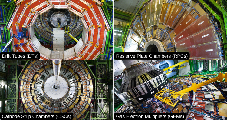
As the name “Compact Muon Solenoid” suggests, detecting muons is one of the most important tasks of CMS. Muons are charged particles that are just like electrons and positrons, but 200 times heavier. We expect them to be produced in the decay of a number of potential new particles; for instance, one of the clearest "signatures" of the Higgs Boson is its decay into four muons.
Because muons can penetrate several metres of material losing little energy, unlike most particles, they are not stopped by any of CMS calorimeters. Therefore, chambers to detect muons are placed in the outer part of the experiment where they are the only particles likely to produce a clear signal.
A particle is measured by fitting a curve to the hits registered in the four muon stations, which are located outside of the magnet coil, interleaved with iron "return yoke" plates. The particle path is measured by tracking its position through the multiple active layers of each station; for improved precision, this information is combined with the CMS silicon tracker measurements. Measuring the trajectory provides a measurement of particle momentum. Indeed, the strong magnetic field generated by the CMS solenoid bends the particle's trajectory, with a bending radius that depends on its momentum: the more straight the track, the higher the momentum.
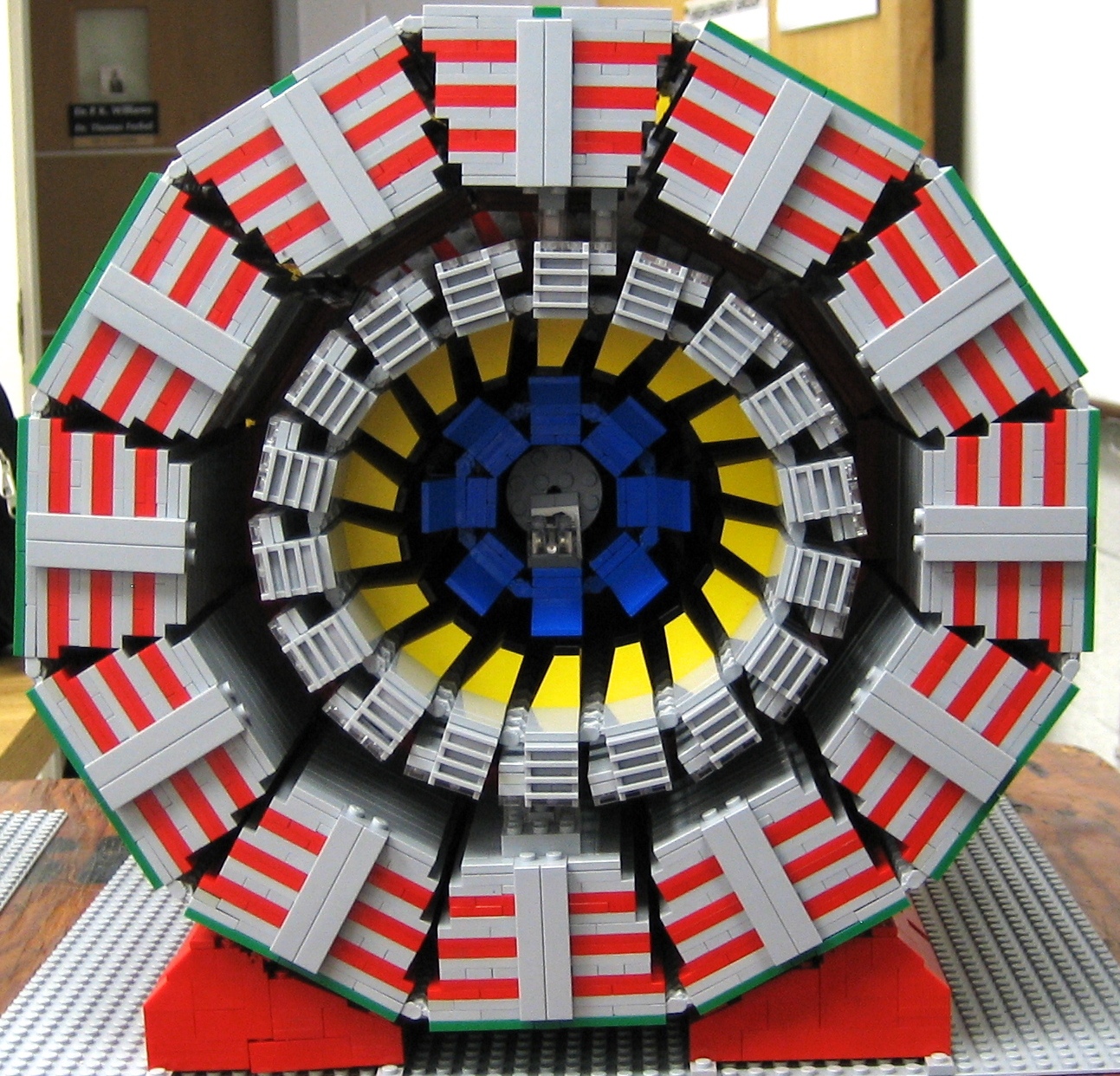
In total there are 1400 muon chambers: 250 drift tubes (DTs) and 540 cathode strip chambers (CSCs) track the particle positions and provide a trigger, while 610 resistive plate chambers (RPCs) and 72 gas electron multiplier chambers (GEMs) form a redundant trigger system, which quickly decides to keep or discard the acquired muon data. Because of the many layers of detector and different specialities of each type, the system is naturally robust and able to filter out background noise.
A muon, in the plane perpendicular to the LHC beams, leaves a curved trajectory in four layers of muon detectors ("stations")
DTs and square-shaped RPCs are arranged in concentric cylinders around the beam line (‘the barrel region’), whilst CSCs, trapezoidal RPCs, and GEMs form the ‘endcap’ disks that “close” the ends of the barrel.
The muon system…
- contains 2 million cathode strip chamber wires each as thin as a human hair;
- is aligned with the central tracker to within one sixth of a millimetre in order for the detectors to work together in reconstructing tracks;
- is made of components built in 15 countries. As of today, the muon system group counts 63 institutions from 22 countries.
Making Tough Chambers
Most of the muon chambers were built in different laboratories around the world before being shipped all the way to CERN, so the chambers needed to be robust as they are meant to act as precision detectors. Their mechanical robustness and performance was extensively tested in several phases of prototyping, design, test beams, assembly and commissioning, both at the respective labs and at CERN.
As a demonstration of their robustness, when physicists overseeing the beam test decided to reposition a chamber, one side of its support structure suddenly fell by more than 30 cm. Such an unprecedented test of robustness had the physicists worry about the fate of that unlucky chamber. Instead, they found it was still "taking data" in spite of its hard drop.
Visit the link for muon system updates: https://cms.cern/index.php/tags/cms-muons-subsystem
Cathode Strip Chambers
Cathode Strip Chambers lucas
Cathode strip chambers (CSC) are used in the endcap disks where the magnetic field is uneven and particle rates are higher than in the barrel.
CSCs consist of arrays of positively-charged anode wires crossed with negatively-charged copper cathode strips within a gas volume. When muons pass through, they knock electrons off the gas atoms, which flock to the anode wires creating an avalanche of electrons. Positive ions move away from the wire and towards the copper cathode, also inducing a charge pulse in the strips, at right angles to the wire direction.
Because the strips and the wires are perpendicular, we get two position coordinates for each passing particle.
In addition to providing precise spatial and timing information, the closely spaced wires make the CSCs fast detectors suitable for triggering. Each CSC module contains six layers making it able to accurately identify muons and match their tracks to those in the tracker.
Visit the link for CSC updates: https://cms.cern/tags/csc
GEMs (Gas Electron Multiplier)
GEMs (Gas Electron Multiplier)
Gas electron multipliers (GEMs) are a new addition to the CMS muon system. They complement existing detectors in the forward regions close to the beampipe, where large radiation doses and high event rates will increase during Phase-2 of the LHC. The harsh environment imposes strict requirements on detector characteristics, requiring technologies with high rate capabilities–hence the choice of GEMs. In the endcaps, the GEM system will improve the measurement of the polar muon bending angle, allowing the trigger of the muon system to cope with the high rates. Additionally, GEMs will further extend the muon system coverage in the very forward regions.
Like the other CMS muon subsystems, GEMs are gaseous detectors. Their key feature is the GEM foil, which consists of a 50 micrometer-thick insulating polymer (polyimide) surrounded on the top and bottom with copper conductors. Throughout the foil, microscopic holes are etched in a regular hexagonal pattern. The CMS GEM chambers consist of two PCBs, containing the gas volume, and a stack of three GEM foils in between. The chambers are filled with an Ar/CO2 gas mixture, which is ionized by incident ionizing particles. A potential difference applied across the foils generates sharp electric fields in the holes. The electrons created during the ionisation process drift towards the foils and are multiplied in the holes. The resulting electron avalanche induces a readout signal on the finely spaced strips.
The CMS GEMs are the first GEM chambers with such a large size (an area of about 0.5 m^2) and the largest GEM system ever installed. A first batch of 144 chambers was installed during Long Shutdown 2 on the first disk of the two endcaps. These chambers will contribute to data-taking from Run-3 of the LHC. Additionally, two more disks of GEM chambers will be installed in each endcap during 2024-2026, before Phase-2 of the LHC.
https://ep-news.web.cern.ch/cms-gems-are-changing-gear
https://ep-news.web.cern.ch/content/demonstrating-capabilities-new-gem
https://home.cern/news/news/experiments/ls2-report-144-new-muon-detecto…
Visit the link for GEM updates: https://cms.cern/tags/gems
Muon Drift Tubes
Muon Drift Tubes lucas
The drift tube (DT) system measures and identifies muon tracks in the barrel part of the detector. Each 4cm-wide tube contains a stretched wire within a gas volume. When a muon or any charged particle passes through the volume, it knocks electrons off the atoms of the gas. These electrons “drift” towards the anode following the electric field, ending up at the positively-charged wire where they are amplified and produce a measurable charge pulse. Each unit or “superlayer” contains four layers of staggered drift cells.
By registering the time taken by the electrons to reach the wire, and since the drift velocity along the cell is a rather constant value, we can identify the exact crossing point of the muon along the cell. Each superlayer provides 4 points in 2D for the muons position.
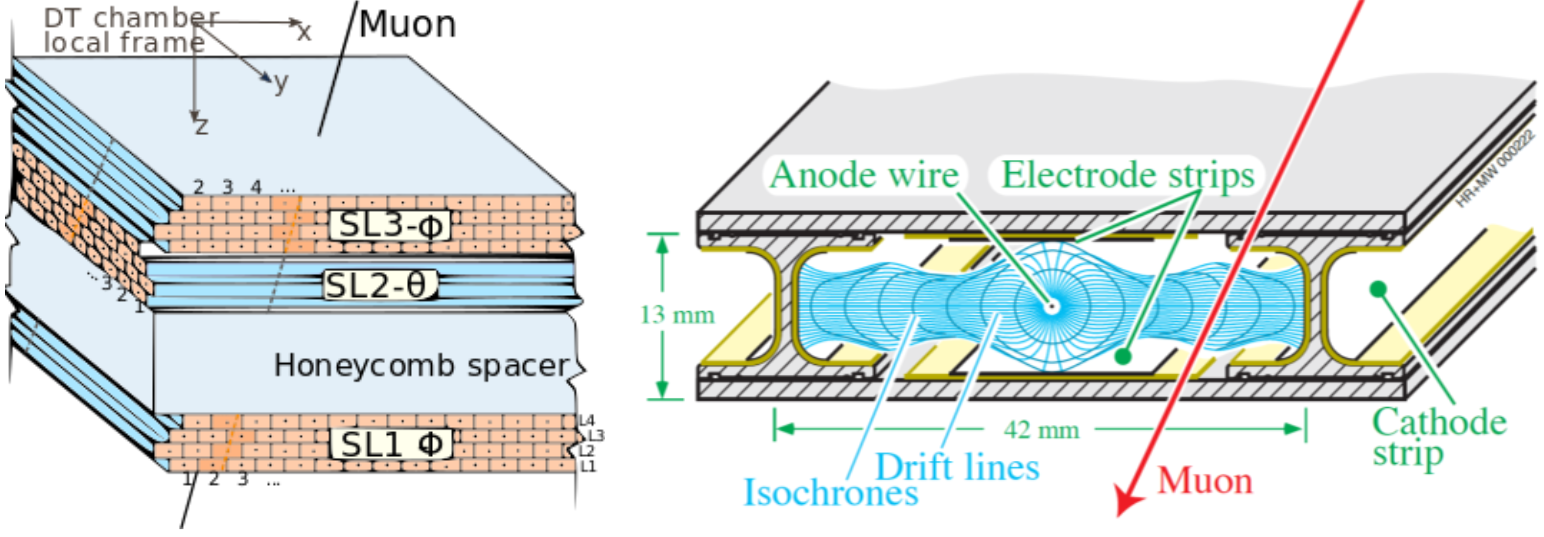
The sizes of DT chambers range from 2m x 2.5m to 4m x 2.5m, approximately. Each chamber consists of 8 or 12 aluminium layers, arranged in two or three superlayers, each up with up to 90 tubes: the middle superlayer measures the coordinate along the direction parallel to the beam and the two outside superlayers measure the perpendicular coordinate, thus providing a combined 3D measurement of the muon track.
Visit the link for Drift Tubes (DTs) updates: https://cms.cern/tags/drift-tubes
Resistive Plate Chambers
Resistive Plate Chambers lucas
Resistive Plate Chambers (RPCs) are fast gaseous detectors that provide a muon trigger system parallel to those of the DTs and CSCs.
RPCs consist of two parallel plates, a positively-charged anode and a negatively-charged cathode, both made of a very high resistivity plastic material and separated by a thin gas volume.
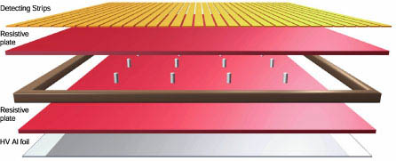
When a muon passes through the chamber, electrons are knocked out of the atoms of the gas. These electrons in turn hit other atoms causing an avalanche of electrons. The electrodes are transparent to the signal (the electrons), which are instead picked up by external metallic strips after a small but precise time delay. The pattern of hit strips gives a quick measure of the muon's momentum, which is then used by the trigger to make immediate decisions about whether the data are worth keeping. RPCs combine a good spatial resolution with a time resolution of just one nanosecond (one billionth of a second).
Visit the link for RPC updates: https://cms.cern/tags/rpc
Energy of Electrons and Photons (ECAL)
Energy of Electrons and Photons (ECAL) lucas
In order to build up a picture of events occurring in the LHC, CMS must measure the energies of emerging particles. Of particular interest are electrons and photons, because of their use in discovering the Higgs boson and other new physics.
The energies of electrons and photons are measured using the CMS electromagnetic calorimeter (ECAL). Measuring their energies with the necessary precision in the very strict conditions of the LHC - a high magnetic field, high levels of radiation, and only 25 nanoseconds between collisions - requires dedicated detector materials.
Lead tungstate crystal is made primarily of metal and is heavier than stainless steel, but with a touch of oxygen in this crystalline form, it is highly transparent and “scintillates” when electrons and photons pass through it. This means it produces light in proportion to the impinging particle’s energy. These high-density crystals produce light in fast, short, well-defined photon bursts that allow for a precise, fast, and fairly compact detector.
Photodetectors, which have been especially designed to work within the high magnetic field, are glued onto the back of each of the crystals to detect the scintillation light and convert it to an electrical signal that is amplified and sent for analysis.
The ECAL, made up of a “barrel” section and two “endcaps”, forms a layer between the tracker and the HCAL. The cylindrical barrel consists of 61,200 crystals formed into 36 “supermodules”, each weighing around three tonnes and containing 1700 crystals. The flat endcaps seal off the barrel at each end and are made up of almost 15,000 more crystals.
For extra spatial precision, the ECAL also contains a preshower detector that sits in front of the endcaps. These allow CMS to distinguish between single high-energy photons (often signs of exciting physics) and the less interesting close pairs of low-energy photons.
The CMS ECAL…
- crystals each weigh 1.5kg but with a volume roughly equal to that of a small coffee cup,
- contains nearly 80,000 such crystals, each of which took two days to grow.
CMS ECAL Technical Design Report
Production Story ....
A Russian factory in a former military complex took on the job of producing most of the crystals, while the remainder were produced in China. It took about ten years to grow all 78,000 crystals to stringent specifications, taking around two days to grow each one. Inside the detector, the crystals face high radiation, so the lead tungstate material had to be carefully chosen and developed.
Crystal Calorimeter
Crystal Calorimeter lucas
CMS uses lead tungstate (PbWO4) for the almost 80,000 crystals: a material with high density that produces scintillation light in fast, small, well-defined photon showers. This means the calorimeter system can be very precise and very compact, fitting within the CMS superconducting magnet. Lead tungstate is also relatively easy to produce from readily available raw materials, and the experience and capability to manufacture them already existed in China and Russia.
Of course, the material also has drawbacks: firstly that the yield of light depends strongly on temperature, a problem given how much heat is released by the readout electronics. To solve the cooling problem a custom-built system maintains the temperature of the 100 tonnes of crystal to within 0.1oC.
Additionally, because the yield of light output is low,the scintillation light [see explanation below] must be captured by photodetectors, converted to an electrical signal, and then amplified. The stronger and now digitised electrical signals are then transmitted through optic fibres. Because the photodetectors also need to be radiation hard and operate within a strong magnetic field, avalanche photodiodes or APDs [see explanation below] were selected for the crystal barrel, and vacuum phototriodes (VPTs) for the endcaps.
Finally, though already fairly radiation resistant after intense research to purify the material, researchers found that lead tungstate would still suffer limited radiation damage inside CMS. However the R&D programme led to a much better understanding of how this damage occurs and found that its main effect is to colour the crystal, affecting how light travels through it.
Knowing this, physicists can ensure that they allow for it in their analysis using a “light monitoring system” during operation that sends pulses of light through each crystal to measure its “optical transmission”. The crystals can reverse radiation damage, or “anneal”, when the accelerator stops (when they are at room temperature) as the warmer temperature naturally shakes atoms back into their ordered structure.
Getting the material right was only one of the challenges for the ECAL team; each crystal had to be cut, machined, polished, tested,and attached to a photodetector. Groups of crystals were then assembled side-by-side in glass-fibre or carbon-fibre “pockets” to form larger structures known as “supercrystals”, “modules”, and “supermodules”.
Crystal Facts
- Crystals measure 2.2 x 2.2 x 23 cm in the barrel and 3 x 3 x 22 cm in the endcaps
- There are exactly 75,848 crystals in the ECAL
- The density of lead tungstate is 8.3 g/cm3
What is scintillation?
When an atom is excited, that is, given energy, an electron goes into a higher orbit and then when it falls back, it releases this energy as a photon. In CMS, when a high-energy electron or photon collides with the heavy nuclei of the ECAL crystals, it generates a shower of electrons, positrons, and photons, and atoms in the material take energy from the passing particles to excite their electrons. The atoms quickly ‘relax’ and the electrons each emit the extra energy as a photon of blue light. A photo device [see below] then picks up these ‘scintillation’ photons and the amount of light generated is proportional to the energy that was deposited in this crystal. This tells us the energy of the incoming electron or photon.
What are photodetectors?
Avalanche photodiodes (APDs) are photodetectors made of semiconducting silicon with a strong electric field applied to them. When a scintillation photon strikes the silicon and knocks an electron out of an atom, the electron is accelerated in the electric field, quickly striking other atoms and knocking electrons off those too. As these are also accelerated, this method will produce an avalanche of electrons with their numbers increasing exponentially. Through this method, APDs are able to produce a very high current in a short time, which is necessary as the lead tungstate crystals give a relatively low light yield for each incident particle. The signal is then amplified, digitised and immediately transported away by fibre optic cables, so that the analysis can be done away from the radiation area.
Crystals in the endcaps use vacuum phototriodes (VPTs) because here the radiation is too high to use silicon photodiodes. As opposed to an APD, a VPT contains three electrodes within a vacuum. Initially, electrons are released when the light strikes atoms in the first electrode in the normal way. Then the voltage difference between electrodes accelerates the electrons into the second electrode (the anode), producing several more electrons, that are all then accelerated to the third (the dynode), releasing a second batch of electrons. Thus this also creates a large current from the initial tiny amount of scintillation light, which is turned into a digital signal and sent along the optic fibres to the upper level readout.
All the photodetectors were glued to the crystals here at CERN, but the finished products are the sum of contributions made by several hundred people and many institutes.
ECAL Preshower
ECAL Preshower lucas
One way the Higgs boson might decay is into high-energy photons and detecting them is one of the ECAL’s primary functions. However, short-lived particles called neutral pions, also produced in collisions, can inadvertently mimic high-energy photons when they decay into two closely-spaced lower energy photons that the ECAL picks up together.
In the endcap regions, where the angle between the two emerging photons from the decay of a neutral pion is likely to be small enough to cause this problem, a preshower detector sits in front of the ECAL to prevent such false signals. The preshower has a much finer granularity than the ECAL with detector strips 2 mm wide, compared to the 3 cm-wide ECAL crystals, and can measure each of the pion-produced particles as a separate photon.
The preshower is made of two planes of lead followed by silicon sensors, similar to those used in the CMS tracker. When a photon passes through the lead layer it causes an electromagnetic shower, containing electron-positron pairs, which the silicon sensors then detect and measure. From this we get a measure of the photon’s energy, while having two detector layers gives us two measurements, allowing us to pinpoint the particle’s position.
When seemingly high-energy photons are then found in the ECAL, we can extrapolate their paths back to the centre of the collision and look for their “hits” in the preshower along the way, adding the energy deposited there to the total energy from the ECAL, and deducing if they really were individual high-energy photons or photon pairs.
Each endcap preshower uses 8 square metres of silicon (a material especially chosen for its accuracy, compactness, ability to deal with radiation, and easiness to handle). The silicon sensors, each measuring about 6.3cm x 6.3cm x 0.3mm and divided into 32 strips, are arranged in a grid in the endcaps to form an approximately circular shape covering most of the area of the crystal endcap. For optimal performance during the lifetime of the experiment, as in the tracker, the silicon detectors must be kept at a temperature of between -10oC and -15oC. However, the nearby ECAL is very sensitive and must be kept within precisely 0.1oC of its (higher) optimal temperature. The preshower must therefore be cold on the inside but warm on the outside, achieved using both heating and cooling systems.
The complete preshower system forms a disc, about 2.5m in circumference with a 50cm diameter hole in the middle (through which the beam pipe passes). This disc is only 20cm thick but manages to squeeze inside two layers of lead, two layers of sensors (and their electronics) as well as the cooling and heating systems – another example of the “compact” nature of CMS.
Energy of Hadrons (HCAL)
Energy of Hadrons (HCAL) lucas
The Hadron Calorimeter (HCAL) measures the energy of “hadrons”, particles made of quarks and gluons (for example protons, neutrons, pions and kaons). Additionally it provides indirect measurement of the presence of non-interacting, uncharged particles such as neutrinos.
Measuring these particles is important as they can tell us if new particles such as the Higgs boson or supersymmetric particles (much heavier versions of the standard particles we know) have been formed.
As these particles decay they may produce new particles that do not leave records of their presence in any part of the CMS detector. To spot these the HCAL must be “hermetic”, that is make sure it captures, to the extent possible, every particle emerging from the collisions. This way if we see particles shoot out one side of the detector, but not the other, with an imbalance in the momentum and energy (measured in the sideways “transverse” direction relative to the beam line), we can deduce that we’re producing “invisible” particles.
To ensure that we’re seeing something new, rather than just letting familiar particles escape undetected, layers of the HCAL were built in a staggered fashion so that there are no gaps in direct lines that a familiar particle might escape through.
The HCAL is a sampling calorimeter [see explanation below] meaning it finds a particle’s position, energy and arrival time using alternating layers of “absorber” and fluorescent “scintillator” materials that produce a rapid light pulse when the particle passes through. Special optic fibres collect up this light and feed it into readout boxes where photodetectors amplify the signal. When the amount of light in a given region is summed up over many layers of tiles in depth, called a “tower”, this total amount of light is a measure of a particle’s energy.
As the HCAL is massive and thick, fitting it into “compact” CMS was a challenge, as the cascades of particles produced when a hadron hits the dense absorber material (known as showers) are large, and the minimum amount of material needed to contain and measure them is about one metre.
To accomplish this feat, the HCAL is organised into barrel (HB and HO), endcap (HE) and forward (HF) sections. There are 36 barrel “wedges”, each weighing 26 tonnes. These form the last layer of detector inside the magnet coil whilst a few additional layers, the outer barrel (HO), sit outside the coil, ensuring no energy leaks out the back of the HB undetected. Similarly, 36 endcap wedges measure particle energies as they emerge through the ends of the solenoid magnet.
Lastly, the two hadronic forward calorimeters (HF) are positioned at either end of CMS, to pick up the myriad particles coming out of the collision region at shallow angles relative to the beam line. These receive the bulk of the particle energy contained in the collision so must be very resistant to radiation and use different materials to the other parts of the HCAL.
The CMS HCAL…
- used over a million World War II brass shell casings from the Russian Navy in making some of its detector components;
- is made up of 36 wedges, each of which weighs as much as 6 African elephants;
- contains over 400 “optical decoder” units, all of which were made by American high school students through the QuarkNet programme.
For a detailed account of the HCAL detector see:
CMS Technical Design Report for the Phase 1 Upgrade of the Hadron Calorimeter https://cds.cern.ch/record/1481837/files/CMS-TDR-010.pdf
CMS HCAL Technical Design Report (1997)
HCAL Sampling Calorimeter
The CMS barrel and endcap sampling calorimeters are made of repeating layers of dense absorber and tiles of plastic scintillator. When a hadronic particle hits a plate of absorber, in this case brass or steel, an interaction can occur producing numerous secondary particles. As these secondary particles flow through successive layers of absorber they too can interact and a cascade or “shower” of particles results. As this shower develops, the particles pass through the alternating layers of active scintillation material causing them to emit blue-violet light. Within each tile tiny optical “wavelength-shifting fibres”, with a diameter of less than 1mm, absorb this light. These shift the blue-violet light into the green region of the spectrum, and clear optic cables then carry the green light away to readout boxes located at strategic locations within the HCAL volume.
A megatile is a layer of tiles whose sizes depend on their spatial location and orientation relative to the collision, chosen so that each receives roughly the same number of particles. Optic fibres fit into grooves cut into the individual tiles. Because the light picked up gives a measure of energy, the gaps between tiles must be filled with a reflective paint to ensure that light produced in each tile cannot escape into others and vice versa.
HCAL module showing sampling layers
The optical signals arrive at the readout boxes from megatile layers. There, signals from successive tiles, one behind the other, are then added optically to form “towers”. This optical summation covers the path of the particle through the HCAL and is a measure of its energy and/or can be an indicator of particle type.
These summed optical signals are converted into fast electronic signals by photosensors called Silicon Photomultipliers (SiPMs) . Special electronics then integrates and encodes these signals and sends them to the data acquisition system for purposes of event triggering and event reconstruction.
SiPMs are photodetectors configured especially for CMS that can operate in any magnetic field and give an amplified response, in proportion to the original signal, for a large range of particle energies. The SiPMs are housed in special readout boxes within the calorimeter volume. Light signals from the calorimeter megatiles are delivered to the SiPMs by special fibre-optic waveguides.
Using Russian navy shells
Using Russian navy shells Anonymous (not verified)
Constructing the endcap HCAL (HE) was the responsibility of the Russian and Dubna (RDMS) groups. The endcaps consist of 17 layers of dense absorber plates that take energy from hadrons and muons emerging from collisions and, together with plastic scintillator plates, give a measure of the particles’ energies.
Because the plates are so large and heavy the teams knew that within the experiment they would be under high levels of stress; yet, to maintain their position relative to the beam pipe for as long as 15 years, they couldn’t bend. The material eventually chosen for the plates was brass, in layers 50 mm thick.
But they needed brass of such high quality that it was practically impossible to find and was an expensive material. When Russian engineers discussed the question, one remembered a study carried out on the properties of brass made for military artillery use that sounded promising.
In Russian military storage there were thousands of shells made of brass that would fit such stringent requirements – all 50 years old, made by the Navy and designed to stand internal high stress and sea storage aboard a 1940s Navy Vessel. The shells could be melted for use in the HCAL.
The first hurdle involved obtaining permission of the Commander of the Navy, never easy, but who in fact agreed fairly quickly. Fifteen navy arsenals began recycling their shells, many being off-loaded from battleships in Murmansk to begin their new scientific life as absorber plates within CMS.
First the shells were sent to a plant in the North of Russia to be disarmed of their explosive contents. The shell casings were then stored at JSC Krasnyj Vyborzhets in St. Petersburg before being melted down and rolled into plates, a difficult process given that the brass was already semi-processed.
Over a million World War II brass shell casings were melted down to make the detector components. But when even this fell short of the massive 600 tonnes of brass needed to make the endcaps, the US agreed to provide a further $1 million in copper (brass being an alloy of copper and zinc) to complete the endcaps. As an example of the international cooperation and mutual trust fostered through this work, even this deal was agreed to on an amicable "handshake" basis.
In Minsk, Belarus, the brass was machined into absorber plates and finally pre assembled into parts of the endcaps, weighing 300 tonnes each, before being sent to CERN. Dollezhal Research and Development Institute of Power Engineering (NIKIET) coordinated the efforts of the Northern Navy and the companies involved, and ran 1400 tests to ensure the material was of high quality and suitable for constructing the endcap HCALs.
The shells and additional copper became a total of 1296 brass pieces, which were delivered to CERN in 2002 and 2003 and have since been installed and tested within CMS.
This project was part of an international agreement to convert Russian military industry into peaceful technology. The recycling of stocks of ship artillery into materials for fundamental research was also symbolic; instead of being used to destroy, the weapons could actively benefit humankind through their contribution to enhanced knowledge and technology.
The crystal story
The crystal story lucas")
A crystal’s journey from creation to its place within the CMS electromagnetic calorimeter is an arduous one: its trials include travelling thousands of miles, being sawed and polished, as well as being heated to 1,165oC and cooled to 18oC.
The journey starts in either a disused military complex in Bogoroditsk, Russia, or the Shanghai Institute of Ceramics (SIC) in China. These two institutions together took on the job of producing the 78,000 crystals to stringent specifications. Crystals are grown around a tiny “seed” - an existing piece of the crystal with the required properties - from a 1,165oC melt of tungsten oxide, lead oxide and “doping” materials, small amounts of other materials that refine the crystals’ properties.
In the Russian method, the seed is pulled from the scalding mixture at a very slow, precise speed that allows the atoms of the melt to arrange into a crystal structure around it. “In 2 or 3 days you have your crystal, which may seem slow but it’s quick compared to geology,” explains Michel Lebeau, an engineer in the crystals team.
Dusting with diamond
But the raw form of the crystal still needs a makeover before it can become one of the sparkling gems we see in the experiment. First it must be cut, ground and polished with diamond. Diamond is the hardest naturally occurring material and can scratch or cut through other crystals, allowing them to be shaped.
A disc covered with fine diamond grains first cuts the crystals’ prismatic accurate shape from its original round form. The second stage, called lapping, involves grinding the rough sides of the crystal as if with diamond sandpaper - a sprayed diamond suspension coats a rotating table, similar to a potter’s wheel, and as the crystals pass over it their surfaces are sanded to a fine matte finish, the flatness of which is controlled to less than a fraction of the width of a human hair.
Finally, to replace the crystals’ cloudy surfaces with a transparent finish, they must now pass over an even finer suspension of diamond, as finer abrasive gives an even smoother surface. The grains used here are in fact so tiny that the polished surface pattern is smaller than the wavelength of light.
To ensure a perfect match with the neighbouring crystals, and to give accurate measures of particle energies, each crystal must comply with very accurate dimensions so that they react in exactly the same way to the light. To make sure of this, the machines that transform the crystals into their sleek final form must also be fine-tuned and precise. After extensive research and development, machines that could give these perfect finishes were designed, fabricated locally and finally shipped, installed and ran at production sites in Russia and China.
Into the detector
For the crystals arriving at the regional centres in CERN and Rome, the welcome was warm but testing was thorough, as each had to be vetted before becoming part of the detector.
The arriving crystals were first unpacked and identified with a barcode before a visual inspection checks for any visible defects. Finally they were registered into a database so they could be followed throughout production and their lifetime in CMS.
Then the dimensions, light transmission and scintillation properties of the crystals were measured, 30 at a time, in an automatic machine (ACCOS) developed in both regional centres. “Usually with a crystal, the beauty of it is that it is coloured. But in our case if crystals are coloured would mean defects and reduced performance,” explains Etiennette Auffray, leader of the crystal assembly at CERN. But in fact only a very small number (less than 1%) of the 1200 crystals processed every month proved unsuitable for use
The vast majority of crystals made it through and were then carefully glued with a photodetector, which will collect and amplify their scintillation light and convert the light into an electrical signal. Each photodetector was then housed in one of 22 slightly different varieties of capsules and glued to one of 34 categories of crystal, in total making 146 different possible combinations: “So there’s a lot of scope to go wrong! We have to check it very carefully after each stage,” explains Auffray.
Then, like building blocks, the crystals were grouped in increasing numbers – for the barrel section they are first packed into lightweight glass-fibre boxes in groups of ten, making a ‘sub-module’. A ‘module’ was then constructed out of 40 or 50 sub-modules.
These modules were then joined by those assembled at the INFN/ENEA Laboratory near Rome, which also carried out the crystal tests and the glueing of photodetectors, in tandem with CERN. These were packed in groups of four, making one of the 36 “supermodules”, each of which weighs 2.5 tonnes.
For the endcaps, 25 crystals are grouped in five-by-five blocks named “supercrystals” and inserted into one of four “Dees”, structures named for their resemblance to the letter D, that fit around the beam allowing easy installation.
Finally the monitoring, cooling system and final electronics were added to the supermodules before they entered the experiment cavern. The cooling system is a record-breaking achievement that keeps the 75,848 crystals within 0.1°C of their optimum temperature to ensure they give a stable and equal response. The flow of water needed to achieve this, recycled through the system, equals 1/10th of the output of Geneva’s Jet d’Eau (Geneva’s fountain).
Inside CMS the supermodules are supported on a strong but lightweight system, designed to add only a minimum amount of material in front of the detector. The structure and crystals are so densely and precisely packed that the remaining space is only 1% of the total. The 2.5-tonne weight of each supermodule is cantilevered from one end so that two-thirds of it is taken at the back and the remaining third on a slender arm of aluminium and glass fibre composite. The maximum expected sag, including in the event of (very improbable) earthquakes, is about half a millimetre. This structure accounts itself for just 10% of the total weight - like a car that carries four passengers weighing just 30kg!
The CRISTAL database
The CRISTAL database achintya
Each CMS crystal is unique even though they are all made from the same material. Its physical characteristics therefore needed to be measured and recorded, not only for the construction phase but also for data collecting itself. Every crystal was labelled with a barcode to identify it and track it through the production and operation stages.
The long time-frame of producing the crystals meant that the means of production as well as the associated electronics evolved over time as improvements were made. Themethods of characterising the crystals themselves and the data formats used for storage also evolved with time. The database into which the information was to be stored would itself need to adapt to these evolving workflows. At the same time, the database must be able to fetch all of the data ever recorded –– i.e. it must be capable of handling legacy datasets –– and must be in a situation to do so in the future when the implementation might potentially be very different. It would also have to handle frequent changes, and so be flexible in design.
No such system existed in the mid-'90s, and so a consortium of scientists from CERN, CNRS (the French National Centre for Scientific Research) and UWE (the University of the West of England) set about developing their own database, giving birth to CRISTAL.
CRISTAL stands for Cooperative Repositories and Information System for Tracking Assembly Lifecycles, and was developed at CERN to manage the data of all CMS ECAL components at each stage of construction.
The CRISTAL database and its underlying technology is extremely novel, and has applications far beyond the world of tracking detector components. CRISTAL is description-driven; that is, the database structures can be modified at any time without affecting any of the collected information. The structures themselves are stored as data too, meaning they can be copied between different databases with the data they define. As a result, any large-scale project with rapidly evolving workflows can benefit from using CRISTAL. It was thus one of the first knowledge-transfer projects undertaken by CERN, and was spun-off into Agilium, a private company that handles business-process management. A second spin-off company called Technoledge is providing database solutions for e-governance, accounting firms, and more.
CRISTAL is another excellent example of technology developed in the course of particle physics research that has since found wide-spread use in industry and elsewhere.
Tracking
Tracking lucas
The measurement of the momentum of particles is crucial in helping us to build up a picture of what happens at the heart of the collision. One method to calculate the momentum of a particle is to track its path through a magnetic field; the more curved the path, the less momentum the particle had. The CMS tracker records the paths taken by charged particles by measuring their positions at a number of points.
The tracker can reconstruct the paths of high-energy muons, electrons, and charged hadrons (particles made up of quarks) as well as see tracks coming from the decay of very short-lived particles such as beauty or “b quarks” that are for example being used to study the differences between matter and antimatter.
The tracker needs to record particle paths accurately yet be lightweight so as to disturb the particles as little as possible. It does this by taking position measurements so accurate that tracks can be reliably reconstructed using just a few measurement points. Each measurement is accurate to 10 µm, a fraction of the width of a human hair. It is also the innermost part of the CMS detector and so receives the highest volume of particles: the construction materials were therefore carefully chosen to resist radiation.
The final design consists of a tracker made entirely of silicon detection elements: the pixels, at the very core of the detector and dealing with the highest intensity of particles, and the silicon microstrip detectors that surround it. As particles travel through the tracker the pixels and microstrips produce tiny electric signals that are amplified and detected. The signals are stored in chips’ memory for several microseconds and then processed before being sent to a laser to be converted into infrared pulses. These are then transmitted over a 100m fibre optic cable for analysis in a radiation-free environment. The tracker uses 40,000 such fibre optic links providing a low power, lightweight way of transporting the signal. Much of the technology behind the tracker electronics came from innovation in collaboration with industry.
The tracker employs sensors covering an area the size of a tennis court, with 135 million separate electronic readout channels: in the pixel detector there are some 6600 connections per square centimetre. Silicon sensors are highly suited to receive many particles in a small space due to their fast response and good spatial resolution.
The CMS strip tracker was installed in CMS in late 2007 and has been in continuous operation since 2008. The original CMS pixel detector was operated during the years 2009 – 2016 and was replaced by the CMS Phase-1 pixel detector in an extended year-end stop 2016/2017.
Visit the link for Pixel Tracker updates: https://cms.cern/tags/tracker
More details about the CMS Tracker can be found in the following selection of documents:
The CMS experiment at the CERN LHC (paper written in ~2008 describing the original CMS experiment as build for LHC Run 1)
The CMS Phase-1 Pixel Detector Upgrade (paper from 2020 describing the Phase-1 pixel detector)
The very original description of the CMS tracking detectors can be found in the Technical Design Report (TDR) from 1998 and 2000, respectively
CMS: The Tracker Project Technical Design Report
The CMS tracker : addendum to the Technical Design Report
While many design aspects have evolved from the original concept, they still provide interesting insights about the challenges for the detectors and how they were thought to be overcome. A few more words on this are in the following paragraph.
Some design history ...
In the very first design sketch of CMS, the tracker section was left blank because it was thought that with the intensity of particles experienced in the LHC it would be impossible to make a tracker that could withstand it. In particular, making readout electronics that could work in this radiation would be a challenge. Hints that the US military, needing such electronics for space travel and nuclear warheads, might have solved some of the potential problems encouraged the team to explore this field.
However, the technology actually came from a most unexpected source; as the military market shrank at the end of the cold war and commercial electronics began to excel, the team took a gamble on a very fine feature manufacturing process, produced for a commercial market, which was not formally in the realm of “radiation hard electronics”. With some modifications, a few simple design tricks and selection of the right technology, it could be as radiation hard as needed. And it was a remarkable success. Eighteen months later the teams had rebuilt the old chips. They had low power consumption, low noise, and high overall performance and on top of this could be easily produced on a large scale, were relatively cheap and thoroughly tested. It was a big breakthrough. The same technology was then also used for the ECAL as well as CMS and ATLAS pixels.
Silicon Pixels
Silicon Pixels lucas
The pixel detector contains 124 million pixels, allowing it to track the paths of particles emerging from the collision with extreme precision. It is also the closest detector to the beam pipe, with cylindrical layers roughly at 3cm, 7cm, 11cm, and 16cm and disks at either end, and so is vital in reconstructing the tracks of very short-lived particles.
Each of the four layers is composed of individual silicon modules, split into little silicon sensors, like tiny kitchen tiles: the pixels. Each of these silicon pixels is 100µm by 150µm, about two hairs' width. When a charged particle passes through a pixel, it disturbs the electrons in the silicon pixel, which results in an electric pulse, or as we call it, a 'hit'. These hits are used to draw the track or trajectory of the charged particle.
By applying a voltage to the sensor, these pulses collect into a small electric signal, which is then amplified by a readout chip for a total of 16 chips per module.
![]()
CMS silicon pixel detector
The detector is made of 2D tiles and has four layers, meaning that we can create a three-dimensional picture of the particle track through the layers.
However, being so close to the collision means that the number of particles passing through is huge: the rate of particles received at 3cm from the beamline is around 600 million particles per square centimetre per second! The pixel detector is able to disentangle and reconstruct all the tracks particles leave behind, and withstand such a pummeling over the duration of the experiment.
Because there are 124 million pixels, the power for each must be kept to a minimum. Even with only around 50 microwatts per pixel, the total power output is 7.5kW- around the same as the energy produced by two electric ovens. So as not to overheat the detector, the pixels are mounted on cooling tubes and kept at -20°C degrees. Operating at this temperature also helps to reduce the effects of the damage to the silicon modules inflicted by the continuous stream of particles.
Visit the link for Pixel Tracker updates
Silicon Strips
Silicon Strips lucas
After the pixels and on their way out of the tracker, particles pass through ten layers of silicon strip detectors, reaching out to a radius of 130 centimetres.
The silicon strip detector consists of four inner barrel (TIB) layers assembled in shells with two inner endcaps (TID), each composed of three small discs. The outer barrel (TOB) – surrounding both the TIB and the TID – consists of six concentric layers. Finally two endcaps (TEC) close off the tracker on either end. Each has silicon modules optimised differently for its place within the detector.
This part of the tracker contains 15,200 highly sensitive modules with a total of about 10 million detector strips read by 72,000 microelectronic chips. Each module consists of three elements: one or two silicon sensors, its mechanical support structure and readout electronics.
The silicon detectors work in much the same way as the pixels: as a charged particle crosses the material it knocks electrons from atoms giving a very small pulse of current lasting a few nanoseconds. This small amount of charge is then amplified by Analogue Pipeline Voltage (APV25) chips, giving us “hits” when a particle passes, allowing us to reconstruct its path. Four or six such chips are housed within a “hybrid”, which also contains electronics to monitor key sensor information, such as temperature, and provide timing information in order to match “hits” with collisions.
Due to the nature of their job, the tracker and its electronics are pummelled by radiation but they are designed to withstand it. To minimise disorder in the silicon this part of the detector is kept at -20oC, to “freeze” any damage and prevent it from perpetuating.
CMS Tracker layers shown in the plane perpendicular to the beam.
Triggering and Data Acquisition
Triggering and Data Acquisition lucasWhen CMS is performing at its peak, about one billion proton-proton interactions will take place every second inside the detector. There is no way that data from all these events could be read out, and even if they could, most would be less likely to reveal new phenomena; they might be low-energy glancing collisions for instance, rather than energetic, head-on interactions.
We therefore need a “trigger” that can select the potentially interesting events, such as those which will produce the Higgs particle, and reduce the rate to just a few hundred “events” per second, which can be read out and stored on computer disk for subsequent analysis.
However, with groups of protons colliding 40 million times per second there are only ever 25 nanoseconds (25 billionths of a second) before the next lot arrive. New waves of particles are being generated before those from the last event have even left the detector! The solution is to store the data in pipelines that can retain and process information from many interactions at the same time. To not confuse particles from two different events, the detectors must have very good time resolution and the signals from the millions of electronic channels must be synchronised so that they can all be identified as being from the same event.
Triggering
Level 1 of the trigger is an extremely fast and wholly automatic process that looks for simple signs of interesting physics, e.g. particles with a large amount of energy or in unusual combinations. This is like a reader simply scanning the headlines of a newspaper to see if anything catches their eye. This way we select the best 100,000 events or “issues” each second from the billion available. For the next test, the higher level trigger, we assimilate and synchronise information from different parts of the detector to recreate the entire event - like collating the different pages to form the full newspaper - and send it to a farm of more than 1000 standard computers.
Here the PCs are like speed readers, who with more detailed information review the information for longer, less than a tenth of a second. They run very complex physics tests to look for specific signatures, for instance matching tracks to hits in the muon chambers, or spotting photons through their high energy but lack of charge. Overall they select 100 events per second and the remaining 99,900 are thrown out. We are left with only the collision events that might teach us something new about physics. Despite the trigger system, CMS still records and analyses several petabytes of data, that’s millions of gigabytes, around the same amount of information as in 10,000 Encyclopaedia Britannica every second, although not all these data are stored.
For a more detailed account of CMS Triggering see:
CMS The TriDAS Project Technical Design Report
The History of CMS Data Acquisition and Triggering
Early History and Key Decisions
The CMS Trigger Group was originally led by Fritz Szoncsó. Wesley Smith was appointed Trigger Project Manager in 1994. One of the earliest decisions made by the group was not to follow existing three-level trigger-system designs.
Just a few years prior to this, in 1985, the ZEUS experiment was the first to decide to use a three-level trigger system which consisted of: pure hardware (L1), mostly custom hardware (L2) and the computer farm (L3). The Tevatron experiments also adopted this architecture.
At CMS, TriDAS (Trigger and Data Acquisition System) Project Manager Sergio Cittolin, TriDAS Institution Board Chair Paris Sphicas and Smith decided not to have a second level trigger. They would take the output of L1 straight to the computer farm for software processing. The main reason for doing this was that the L2 hardware was too restrictive. It was not fully programmable, and was only used at the time because there was no telecom switch that could convey the full L1 output of 100 kHz of 1 MB events to the farm.
However, Cittolin, studying technology trends and extrapolating world-wide computing network infrastructure, was convinced that a switch with the required bandwidth would be available and affordable by the year 2000. So, when the technical proposal was written in ’94-’95, a plan to go from L1 to the computer farm was laid out.
When the technical proposal was presented to the LHC Experiments Committee (LHCC) in 1994, a different approach was adopted to deal with the bandwidth problem, in order to pass the reviews: The proposal said that 10% of the data would go through the switch for processing and would be used as a basis to knock down the rate by a factor of 10 — sufficient for the switches of 1994 to handle! This 10% — including main calorimeter information, summary of tracking information and so on — would then be used to decide whether to keep the event or not. The group hoped, though, that they would not have to face the problem at all.
Prototyping and testing followed until the Technical Design Report (TDR) was published in 1999/2000 and defended in front of the LHCC. By 2002, network switches with the required bandwidth were available and the problem was solved.
Consequences of Two-Level Trigger
One consequence of the decision was that L1 has to be more efficient than in previous systems in order to perform certain tasks traditionally performed by L2.
Prior to the CMS Trigger, triggers were designed to count objects: the number of electrons/muons over a certain threshold and the like, providing a histogram. In CMS, characteristics of objects, including their energy and co-ordinates would be retained, which required sorting of the objects so that only the prime candidates would be selected.
However, sorting consumes time. Which is why the latency — trigger processing time — is longer than it would have been for the L1 trigger in a three-level trigger system. Custom chips were built for the calorimeter trigger to perform the sorting fast enough.
The upside to this, Smith says, is that instead of asking how many jets or electrons we have, we can ask, “Is there an electron above an ET threshold back-to-back with a jet above that threshold?” and other such questions. This had never been done before and almost allows CMS to perform offline operations at the L1 stage itself.
Wesley Smith adds: “I think it’s been proven that we really built it almost optimally. It was a long extrapolation but I think in retrospect it’s a fairly successful design. The higher level triggers worked out quite well, are well designed, and showed the flexibility of the system. In the end, if you look back at the history, we did make the right decisions. Although at the time, as always, it was not clear.”
How CMS detects particles
How CMS detects particles lucasEach particle that emerges from an LHC collision is like a piece of a puzzle, with some of these pieces breaking up further as they travel away from the collision. Each leaves a trace in the detector and CMS’s job is to gather up information about every one - perhaps 20, 100 or even 1000 puzzle tracks - so that physicists can put the jigsaw back together and see the full picture of what happened at the heart of the collision.
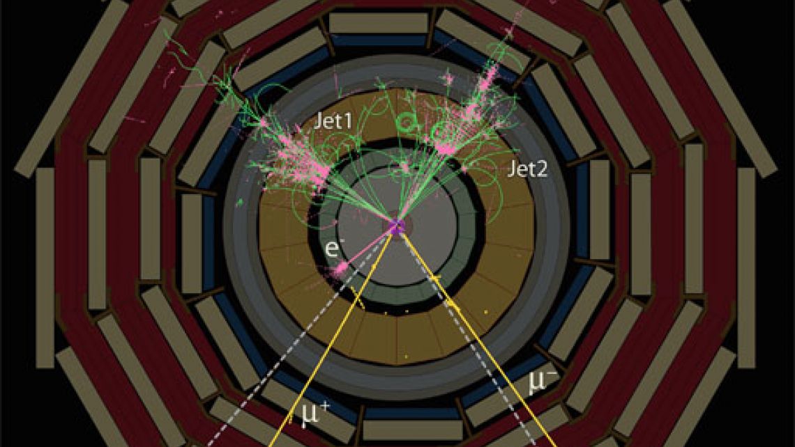
This event shows the production of a supersymmetric particle. The decay of the particle is such that every single layer of CMS is needed to detect the full range of emerging particles: electrons, muons, neutrinos and jets, produced by quarks.
To do this, CMS consists of layers of detector material that exploit the different properties of particles to catch and measure the energy or momentum of each one. New particles discovered in CMS will be typically unstable and rapidly transform into a cascade of lighter, more stable and better-understood particles.
NOTE: A Powerpoint version of the above slice animation can be found here.
A particle emerging from the collision and travelling outwards will first encounter the tracking system, made of silicon pixels and silicon strip detectors. These accurately measure the positions of passing charged particles allowing physicists to reconstruct their tracks. Charged particles follow spiralling paths in the CMS magnetic field and the curvature of their paths reveal their momenta.
The energies of the particles will be measured in the next layer of the detector, the so-called calorimeters. Electrons, photons and jets (sprays of particles produced by quarks) will all be stopped by the calorimeters, allowing their energy to be measured.
The first calorimeter layer is designed to measure the energies of electrons and photons with great precision. Since these particles interact electromagnetically, it is called an electromagnetic calorimeter (ECAL).
Particles that interact by the strong force, hadrons, deposit most of their energy in the next layer, the hadronic calorimeter (HCAL). The only known particles to penetrate beyond the HCAL are muons and weakly interacting particles such as neutrinos. Muons are charged particles, which are then tracked further in dedicated muon chamber detectors. Their momenta are also measured from the bending of paths in the CMS magnetic field. Neutrinos, however, are neutral and since they hardly interact at all they will escape detection. Their presence can nevertheless be inferred. By adding up the momenta of all the detected particles, and assigning the missing momentum to the neutrinos, CMS physicists will be able to tell where these particles were.
Particles travelling through CMS thus leave behind characteristic patterns, or ‘signatures’, in the different layers, allowing them to be identified (see figure). The data is passed from CERN to centres around the world where analysts then reconstruct the “event” and the presence of any new particles can be inferred.
Medical Imaging
Medical ImagingFrom Detecting Particles to Detecting Tumours
The CMS’s electromagnetic calorimeter uses scintillating crystal technology that is similar to the technology used in Positron Emission Tomography (PET) scans.
PET is a medical imaging device that uses antimatter to observe metabolic processes in the body, such as cancerous tumours. In this process, a radioactive “tracer” is injected into the body where it is absorbed by the targeted tissue. An isotope in the tracer will decay and produce antimatter particles called positrons, which will annihilate with an electron (its antimatter counterpart) in the body and release a pair of photons that fly in opposite directions. The ring-shaped PET detector surrounding the body detects the photons and uses their positions to reconstruct a 3D image of the target area. This image reveals information about the tissue by mapping the tracers concentrated there.
Credit: Imperial College London
The Crystal Clear Collaboration (CCC) was founded at CERN in 1990 to search for a suitable scintillator for use in the Large Hadron Collider’s electromagnetic calorimeter (ECAL). Among the various studied crystals, lead tungstate was found to be the most suitable and was then used by CMS and ALICE.
The CMS’s ECAL measures the energies of photons and electrons that are produced by high-energy collisions in the LHC. When electrons or high-energy photons pass through the ECAL, the scintillating crystals produce bursts of optical photons in proportion to the particles’ energy. These collisions in the LHC are like high-energy versions of the electron-positron collisions that occur in the body during a PET scan.

Since 1996, the CCC has been working in the development of high-performance PET systems in addition to their generic research to better understand scintillator properties. One of these systems, ClearPET, is a small animal PET scanner that allows researchers to study the effects of radiopharmaceuticals on the brains of small animals.

In continuation of their PET research, the CCC launched the ClearPEM (Positron Emission Mammography) project in 2002 to develop a dedicated breast PET scanner. ClearPEM can detect cancer lesions as small as 1.3 millimetres, hopefully leading to earlier detection and subsequent lower breast cancer mortality. Its photodetector (the device that converts light from the scintillating crystals into electrical signals) is the same avalanche photodiode as the one developed for CMS’s ECAL! The ClearPEM system has gone through successful clinical trials in hospitals in Coimbra, Portugal, Marseille, France, and Monza, Italy.
More recently, some members of the CCC within an FP7 European project, EndoTOFPET-US (Endoscopic Time-Of-Flight PET & Ultrasound), developed a “time-of-flight” PET for the improved detection of pancreas and prostate cancer. The time-of-flight PET takes into account an additional measurement to more accurately triangulate the photons’ point of annihilation: the difference in photon arrival times to each side of the detector, or “time-of-flight”. This means it can achieve better-quality images in less time or reduce the dose of the radiopharmaceutical injected in the patient.
The development of faster detection being carried out by CCC would not only be valuable for medical imaging but also holds promise for future components of the CMS detector.
Find out more:
- Crystal Clear celebrates 25 years of success, Etiennette Auffray (2016), CERN Courier
- ClearPEM clarifies breast cancer diagnosis, Benjamin Frisch (2013), CERN Courier
- Crystals against cancer, CERN Bulletin (2009)
- ClearPET offers improved insight into animal brains, Stefaan Tavernier (2005), CERN Courier
- “R & D proposal for the study of new fast and radiation hard scintillators for calorimetry at LHC”, Crystal Clear Collaboration (1991)
Contact person: Etiennette Auffray, CERN
What is CMS?
What is CMS? lucasAbout CMS
The Large Hadron Collider (LHC) at CERN smashes protons together at close to the speed of light with seven times the energy of the most powerful accelerators built up to now. Some of the collision energy is turned into mass, creating new particles which are observed in the Compact Muon Solenoid (CMS) particle detector. CMS data is analyzed by scientists around the world to build up a picture of what happened at the heart of the collision. This will help us answer questions such as: "what is the Universe really made of and what forces act within it?" and "what gives everything substance?" Such research increases our basic understanding and may also spark new technologies that change the world we live in.

The LHC smashes groups of protons together at close to the speed of light: 40 million times per second and with seven times the energy of the most powerful accelerators built up to now. Many of these will just be glancing blows but some will be head on collisions and very energetic. When this happens some of the energy of the collision is turned into mass and previously unobserved, short-lived particles – which could give clues about how Nature behaves at a fundamental level - fly out and into the detector.
CMS is a particle detector that is designed to see a wide range of particles and phenomena produced in high-energy collisions in the LHC. Like a cylindrical onion, different layers of detectors measure the different particles, and use this key data to build up a picture of events at the heart of the collision.
Scientists then use this data to search for new phenomena that will help to answer questions such as: What is the Universe really made of and what forces act within it? And what gives everything substance? CMS will also measure the properties of previously discovered particles with unprecedented precision, and be on the lookout for completely new, unpredicted phenomena.
Why is CMS so big?
Why is CMS so big? lucasIt may seem strange that to record the Universe’s tiniest constituents we need the world’s most powerful machines and detectors. But the detector needs to be big because the particles flying out of the collisions have such high energies that it takes big distances to absorb them. And the higher the energy, the greater the amount of material needed.
A bigger detector also means the possibility of obtaining more accurate measurements. To measure the momentum of a particle we track its path through a magnetic field, as the greater the momentum the less it bends within it. The bigger the detector, the more measurements can be taken in “tracking” the particle, meaning more accuracy in the momentum calculation.
As this measurement gets harder with more energetic particles, to maintain the required accuracy we need a strong magnetic field to bend the paths as much as possible. This brings with it other size requirements, as the field needs to be guided and contained by an iron “return yoke”. The amount of iron grows in size in proportion with the magnetic field, so for the 4 Tesla CMS magnetic field, 100,000 times stronger than that of the Earth, we use 12,000 tonnes of iron.
As a result of all of this, CMS is 15 metres in diameter and weighs around the same as 30 jumbo jets or 2,500 African elephants. And though it is the size of a cathedral, it contains detectors as precise as Swiss watches.
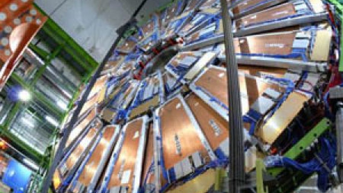
CMS detector in a cavern 100 m underground at CERN's Large Hadron Collider.